
Oil outlet filter screen differential pressure high pressure control calibration device

A calibration device and filter screen technology, which is applied to measuring devices, measuring fluid pressure, instruments, etc., can solve the problems of unqualified filtering effect, unqualified oil quality of EH oil, failure to calibrate, waste of spare parts, etc.

Pending Publication Date: 2021-04-30
HUANENG YIMIN COAL POWER CO LTD
View PDF4 Cites 0 Cited by
  • Summary
  • Abstract
  • Description
  • Claims
  • Application Information

AI Technical Summary

Problems solved by technology

[0002] The EH oil filter differential pressure switch is mainly used in the differential pressure measurement before and after the filter of the EH oil system in the first and second phases of our factory. The purpose is to judge whether the EH oil filter is clogged by measuring the differential pressure before and after the filter and prevent the filter from appearing. Insufficient oil supply due to clogging and poor filtering effect due to filter failure, resulting in unqualified EH oil quality. Since the sampling position and joints of this differential pressure switch are special models, the existing instruments and joints in the laboratory cannot be calibrated According to the experience, when the EH oil system filter differential pressure alarmed on site, the thermal engineering professional could not determine whether the alarm was true or false, and could only judge whether the alarm was correct by replacing the filter element. On the one hand, it brought inconvenience to the judgment of the actual operating conditions of the EH oil system. On the other hand, it may cause waste of spare parts

Method used


Image

  • Oil outlet filter screen differential pressure high pressure control calibration device
  • Oil outlet filter screen differential pressure high pressure control calibration device
  • Oil outlet filter screen differential pressure high pressure control calibration device

Examples


Embodiment 1

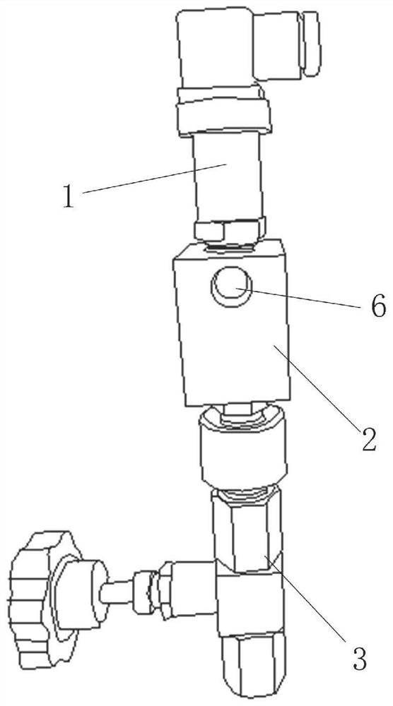
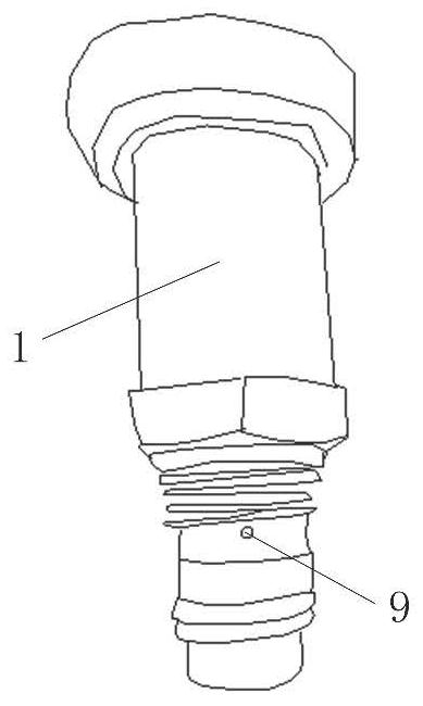
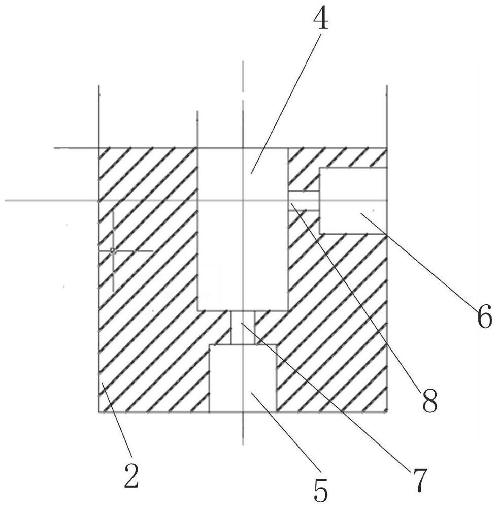
[0021] See Figure 1-Figure 5 , the embodiment of the present invention provides an oil outlet filter screen differential pressure high pressure control verification device 2, comprising: a differential pressure switch 1, the differential pressure switch 1 is used to detect the oil pressure at the oil outlet of the oil pipe 3; A verification device 2 is provided at the outlet of the differential pressure switch 1, the inlet of the verification device 2 communicates with the outlet of the differential pressure switch 1, and the outlet of the verification device 2 communicates with the oil outlet pipe 3 ; The verification device 2 is a block structure with first threaded hole 4 and second threaded hole 5 respectively at both ends, and the side wall of the block structure is provided with the first threaded hole 4 A connected third threaded hole 6, a first passage 7 is arranged between the first threaded hole 4 and the second threaded hole 5, and one end of the first passage 7 co...


PUM


Abstract

The invention provides an oil outlet filter screen differential pressure high pressure control calibration device, which comprises a differential pressure switch used for detecting oil pressure at an oil outlet of an oil outlet pipe; a verifying device is arranged at an outlet of the differential pressure switch, an inlet of the verifying device is communicated with an outlet of the differential pressure switch, and an outlet of the verifying device is communicated with the oil outlet pipe; the verifying device is of a blocky structure, a first threaded hole and a second threaded hole are formed in the two ends of the blocky structure respectively, a third threaded hole communicated with the first threaded hole is formed in the side wall of the blocky structure, a first channel is formed between the first threaded hole and the second threaded hole, and a second pipeline is arranged between the first threaded hole and the third threaded hole. The blocky structure is in threaded connection with the differential pressure switch through the first threaded hole; and the blocky structure is in threaded connection with the oil outlet pipe through the second threaded hole. The device of the scheme can be connected with a laboratory standard instrument to realize the verification of the differential pressure switch, and the problem that the joint cannot be verified in the prior art is solved.

Description

technical field [0001] The invention relates to the technical field of oil system outlet filter screen differential pressure pressure control calibration, in particular to an oil outlet filter screen differential pressure high pressure control calibration device. Background technique [0002] The EH oil filter differential pressure switch is mainly used in the differential pressure measurement before and after the filter of the EH oil system in the first and second phases of our factory. The purpose is to judge whether the EH oil filter is clogged by measuring the differential pressure before and after the filter and prevent the filter from appearing. Insufficient oil supply due to clogging and poor filtering effect due to filter failure, resulting in unqualified EH oil quality. Since the sampling position and joints of this differential pressure switch are special models, the existing instruments and joints in the laboratory cannot be calibrated According to the experience,...

Claims


Application Information

Patent Timeline
Patent Type & Authority Applications(China)
IPC IPC(8): G01L27/00
CPCG01L27/002
Inventor 王志鹏杨立勇包永胜孙天秀董树鑫
Owner HUANENG YIMIN COAL POWER CO LTD
Learn More