
Encoder coded disc eccentricity detection equipment and eccentricity adjusting method

A technology of eccentricity detection and eccentricity adjustment, which is applied in the field of encoder assembly and adjustment, and can solve problems such as misalignment of rotating shafts and angular position errors

Active Publication Date: 2021-04-30
长春长光启衡传感技术有限公司
View PDF11 Cites 1 Cited by
  • Summary
  • Abstract
  • Description
  • Claims
  • Application Information

AI Technical Summary

Problems solved by technology

Theoretically, the geometric central axis of the circular code disc should coincide with the rotational axis of the rotating shaft, but in the actual production and assembly process, often due to technological problems, the geometric center of the disc and the rotating axis of the rotating shaft do not coincide, resulting in actual There is an error in the measured angular position, the so-called eccentricity error

Method used


Image

  • Encoder coded disc eccentricity detection equipment and eccentricity adjusting method
  • Encoder coded disc eccentricity detection equipment and eccentricity adjusting method
  • Encoder coded disc eccentricity detection equipment and eccentricity adjusting method

Examples


Embodiment Construction

[0038] At present, the conventional detection and adjustment method for the eccentricity error of the rotary encoder is carried out through a microscope. The field of view of the microscope is circular, and generally there will be a cross-shaped baseline at the center of the circular field of view. When using a microscope to adjust the relative offset between the rotary shaft and the center of the code disc in the rotary encoder, the microscope can be directly above the rotary encoder to face the code disc, and the center of the cross-shaped baseline of the circular field of view is aligned with the rotary shaft. The offset between the base circle of the circular field of view and the circular code track on the code wheel can determine the offset of the code wheel relative to the rotating shaft, and thus adjust the relative eccentricity between the code wheel and the rotating shaft . Although this adjustment method can realize the eccentric adjustment between the code disc an...


PUM


Abstract

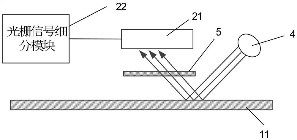
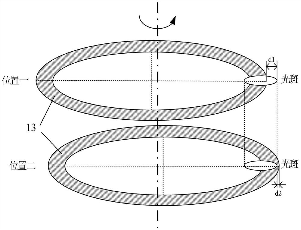
The invention discloses encoder coded disc eccentricity detection equipment. The equipment comprises a rotating device used for driving a rotating shaft of an encoder to be detected to rotate, a first optical grating which is fixedly arranged on a coded disc of the encoder to be tested and is a circular optical grating or a circular optical grating which is concentric with a code channel of the coded disc, a light source, a second optical grating fixed in relative position with the rotating shaft and a Moire fringe detector, wherein light output by the light source passes through the first optical grating and the second optical grating to generate Moire fringes changing along with rotation of the coded disc; the Moire fringe detector is used for detecting the Moire fringes and outputting eccentric data according to the Moire fringes so as to determine the eccentricity of the coded disc relative to the rotating shaft. According to the invention, the eccentric data of the coded disc relative to the rotating shaft is determined by utilizing the Moire fringes formed by the first optical grating and the second optical grating, so that the eccentric error of the encoder is reduced to a great extent, and the measurement precision of the encoder is improved. The invention further provides an encoder eccentricity adjusting method which has the above beneficial effects.

Description

technical field [0001] The invention relates to the technical field of encoder assembly and adjustment, in particular to an encoder code disc eccentricity detection device and an encoder code disc eccentricity adjustment method. Background technique [0002] As a precision digital measurement device, the rotary encoder can realize high-precision detection of the monitoring system. It has the advantages of high measurement accuracy, small size, light weight, reliable use, and easy maintenance. It is widely used in CNC machine tools, robots, textiles, and medical treatment. and elevators. [0003] With the wide application of rotary encoders, people's requirements for the accuracy of rotary encoders are getting higher and higher. For rotary encoders, the eccentricity error of the circular code disc is one of the main sources of measurement errors. Inside the rotary encoder, the rotating shaft of the rotary encoder drives the circular code disc to rotate, and the angular posi...

Claims


Application Information

Patent Timeline
Patent Type & Authority Applications(China)
IPC IPC(8): G01B11/27
CPCG01B11/27
Inventor 吴宏圣吕旸石林朴景利王海平
Owner 长春长光启衡传感技术有限公司
Learn More