Rotary kiln riding wheel bearing set lubricating device

A lubricating device and oil-feeding technology, which is applied in lubricating parts, engine lubrication, engine components, etc., can solve the problems of enterprise loss, accelerated wear of sliding parts, and large consumption

Pending Publication Date: 2021-04-30
NANJING KISEN INT ENG
View PDF0 Cites 2 Cited by
  • Summary
  • Abstract
  • Description
  • Claims
  • Application Information

AI Technical Summary

Problems solved by technology

[0002] The rotary kiln supporting wheel bearing group is the supporting device in the cement rotary kiln. The ambient temperature is high, and the lubricating oil in the existing supporting roller bearing group is too high in temperature and consumes a lot. Once the lubricating oil evaporates a lot, the viscosity will drop and the lubrication effect cannot be effectively achieved. To solve the problem of getting started, only It is manually replenished regularly, but the operation is cumbersome and inconvenient to use; if the temperature of the lubricating oil is high for a long time, the viscosity of the lubricating oil will decrease, which will cause the lubricating oil to lose its lubricating effect; in addition, the high load will easily cause internal sliding parts The wear and tear is accelerated, resulting in more tiny iron filings mixed in the lubricating oil. After the tiny iron filings continue to circulate with the lubricating oil, the wear of the bearing and oil seal will be aggravated, which will shorten the service life of the supporting roller bearing group, and even cause the supporting wheel bearing Group failure, which will lead to the shutdown of the rotary kiln, resulting in interruption of production. Since the rotary kiln is in the key part of the entire cement production line, its shutdown will lead to the stop of the entire cement production line, which will bring immeasurable losses to the enterprise. It is urgent to wait for a solution

Method used


Image

  • Rotary kiln riding wheel bearing set lubricating device
  • Rotary kiln riding wheel bearing set lubricating device

Examples


Embodiment Construction

[0012] Unless otherwise defined, the technical terms or scientific terms used in the present invention shall have the usual meanings understood by those skilled in the art to which the present invention belongs. "First", "second" and similar words used in the present invention do not indicate any order, quantity or importance, but are only used to distinguish different components. "Comprising" or "comprising" and similar words mean that the elements or items appearing before the word include the elements or items listed after the word and their equivalents, without excluding other elements or items. Words such as "connected" or "connected" are not limited to physical or mechanical connections, but may include electrical connections, whether direct or indirect. "Up", "Down", "Left", "Right" and so on are only used to indicate the relative positional relationship. When the absolute position of the described object changes, the relative positional relationship may also change acc...


PUM


Abstract

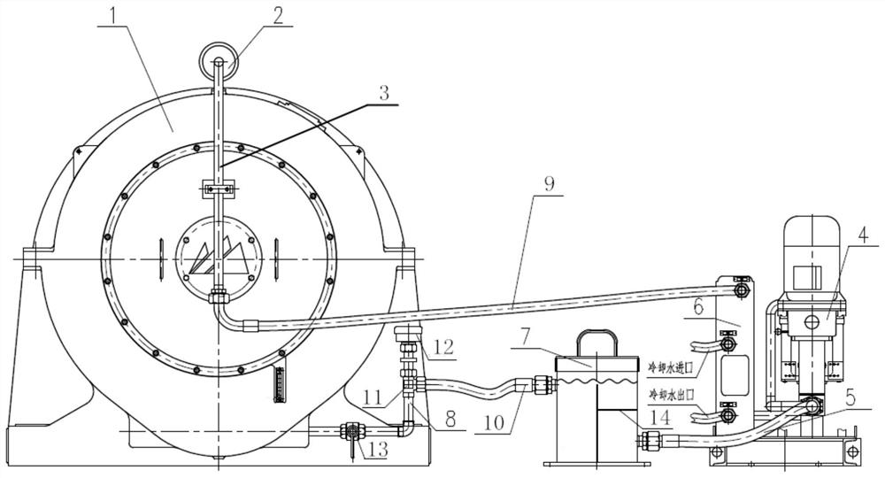
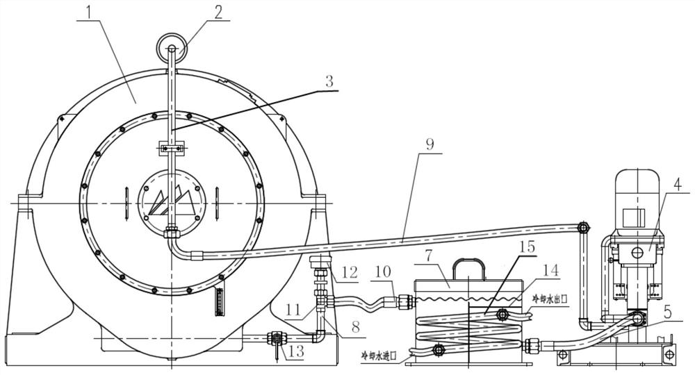
The invention relates to a rotary kiln riding wheel bearing set lubricating device. The device comprises an oil inlet hard pipe, an oil inlet hose, a metering pump, an oil tank, a first oil outlet hose, a second oil outlet hose, an oil outlet hard pipe, a tee joint and a ventilation cap. One end of the oil inlet hard pipe is connected with one end of the oil inlet hose, the other end of the oil inlet hose is connected with an oil outlet of the metering pump, an oil inlet of the metering pump is connected with one end of the first oil outlet hose, the other end of the first oil outlet hose is connected with an oil inlet of the oil tank, an oil outlet of the oil tank is connected with one end of the second oil outlet hose, and the other end of the second oil outlet hose, one end of the oil outlet hard pipe and the ventilation cap are respectively connected to three interfaces of the tee joint; a plurality of magnetic nets are further arranged in the oil tank; and the device further comprises an oil cooler connected in series between the oil inlet hose and the metering pump, or a cooling coil arranged in the oil tank. According to the rotary kiln riding wheel bearing set lubricating device, the oil temperature of the lubricating oil is remarkably reduced, the consumption of the lubricating oil is reduced, and the lubricating oil in a riding wheel bearing set can be kept at a lower oil temperature for a long time to ensure a good lubricating effect.

Description

technical field [0001] The invention relates to a lubricating device for a supporting wheel bearing group of a rotary kiln. Background technique [0002] The rotary kiln supporting wheel bearing group is the supporting device in the cement rotary kiln. The ambient temperature is high, and the lubricating oil in the existing supporting roller bearing group is too high in temperature and consumes a lot. Once the lubricating oil evaporates a lot, the viscosity will drop and the lubrication effect cannot be effectively achieved. To solve the problem of getting started, only It is manually replenished regularly, but the operation is cumbersome and inconvenient to use; if the temperature of the lubricating oil is high for a long time, the viscosity of the lubricating oil will decrease, which will cause the lubricating oil to lose its lubricating effect; in addition, the high load will easily cause internal sliding parts The wear and tear is accelerated, resulting in more tiny iro...

Claims


Application Information

Patent Timeline
Patent Type & Authority Applications(China)
IPC IPC(8): F16N7/38F16N7/40F16N21/00F16N39/02F16N39/06
CPCF16N7/38F16N7/40F16N21/00F16N39/02F16N39/06
Inventor 崔恒波李刚康宇周之炎王小祥徐洪源
Owner NANJING KISEN INT ENG
Why Eureka
Try Eureka