


Quick Research
Generate reliable direction feasibility study reports for your R&D in just a few steps.

Technical Q&A
Discover and master advanced knowledge NOW. Basics, ideas, possibilities, all at once.

Find Solutions
As an expert in R&D theories, this can generate solutions to your technical problems instantly.

Evaluate Feasibility
Analyze your overall solution with one click, know your potential R&D risks in advance.

Monitor Landscape
Get weekly tech updates, stay abreast of the latest tech innovations and key insights.
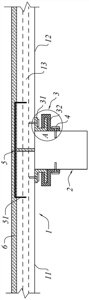
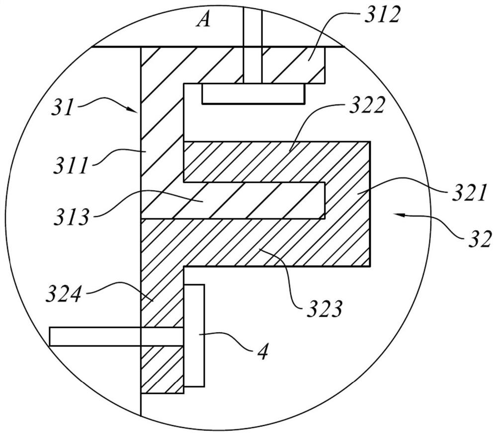
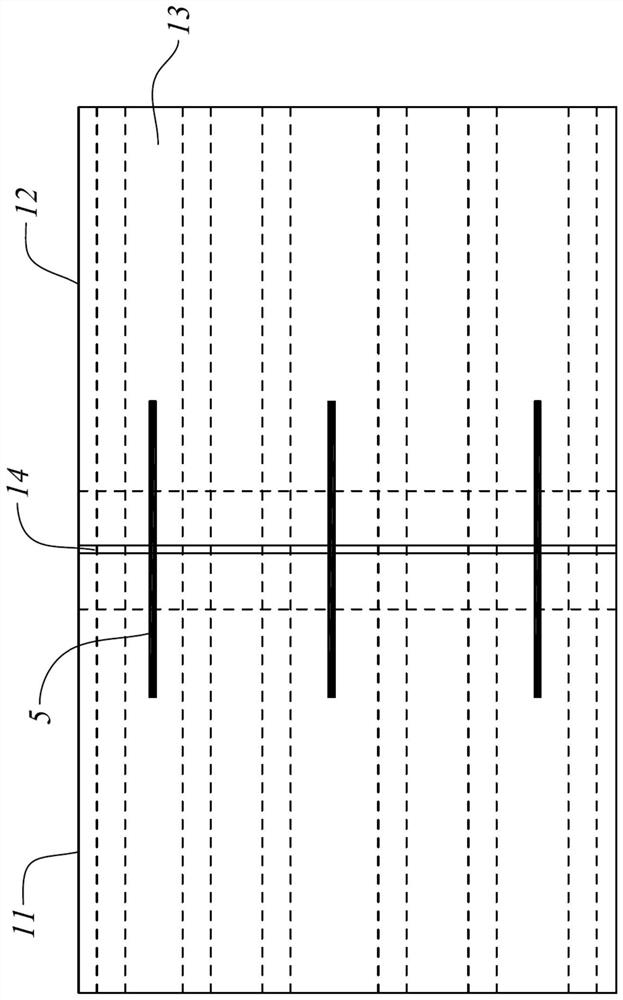
Connection structure of prefabricated slab and bay beam and its construction method
A technology for connecting structures and prefabricated panels, applied in the direction of floor slabs, building components, building structures, etc., can solve the problems of unfavorable earthquake resistance, structural integrity can not meet the corresponding requirements, prefabricated panels and bay beams are not firmly lapped, etc. Improve synergistic deformation ability, avoid local or overall collapse, and the effect of simple construction methods
- Summary
- Abstract
- Description
- Claims
- Application Information
AI Technical Summary
Problems solved by technology
Method used
Image

Examples
Embodiment Construction
[0035] The present invention will be described in detail below with reference to the various embodiments shown in the accompanying drawings. However, these embodiments do not limit the present invention, and the structural, method, or functional transformations made by those of ordinary skill in the art based on these embodiments are all included in the protection scope of the present invention.
[0036] It should be noted that when an element is referred to as being "fixed to" another element, it can be directly on the other element or intervening elements may also be present. When an element is referred to as being "connected" to another element, it can be directly connected to the other element or intervening elements may also be present. In the illustrated embodiment, the directional representations, ie, up, down, left, right, front and rear, etc., are relative, and are used to explain that the structure and movement of the various components in this application are relati...
PUM
 Abstract
Description
Claims
Application Information
 - R&D Engineer
- R&D Manager
- IP Professional
- Industry Leading Data Capabilities
- Powerful AI technology
- Patent DNA Extraction
Browse by: Latest US Patents, China's latest patents, Technical Efficacy Thesaurus, Application Domain, Technology Topic, Popular Technical Reports.
© 2024 PatSnap. All rights reserved.Legal|Privacy policy|Modern Slavery Act Transparency Statement|Sitemap|About US| Contact US: help@patsnap.com