Clamping device for component machining

A clamping device and component technology, which is applied in the field of clamping devices for component processing, and can solve problems such as lifting and disengaging

Inactive Publication Date: 2021-04-30
郑斗
View PDF0 Cites 1 Cited by
  • Summary
  • Abstract
  • Description
  • Claims
  • Application Information

AI Technical Summary

Problems solved by technology

[0003] The purpose of the embodiments of the present invention is to provide a clamping device for component processing, which aims to solve the problem of manual lifting and disengagement

Method used


Image

  • Clamping device for component machining
  • Clamping device for component machining
  • Clamping device for component machining

Examples


Embodiment Construction

[0017] In order to make the object, technical solution and advantages of the present invention clearer, the present invention will be further described in detail below in conjunction with the accompanying drawings and embodiments. It should be understood that the specific embodiments described here are only used to explain the present invention, not to limit the present invention.

[0018] The specific implementation of the present invention will be described in detail below in conjunction with specific embodiments.

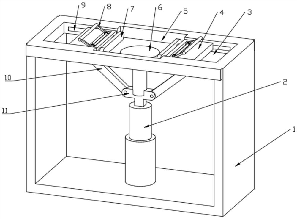
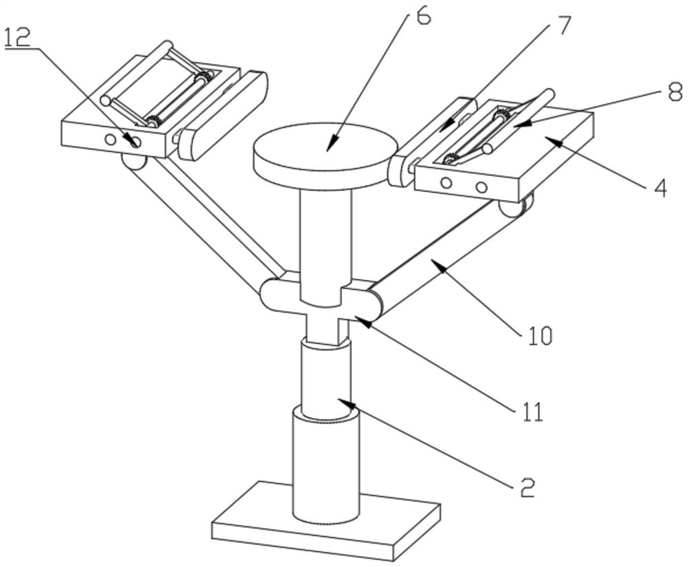
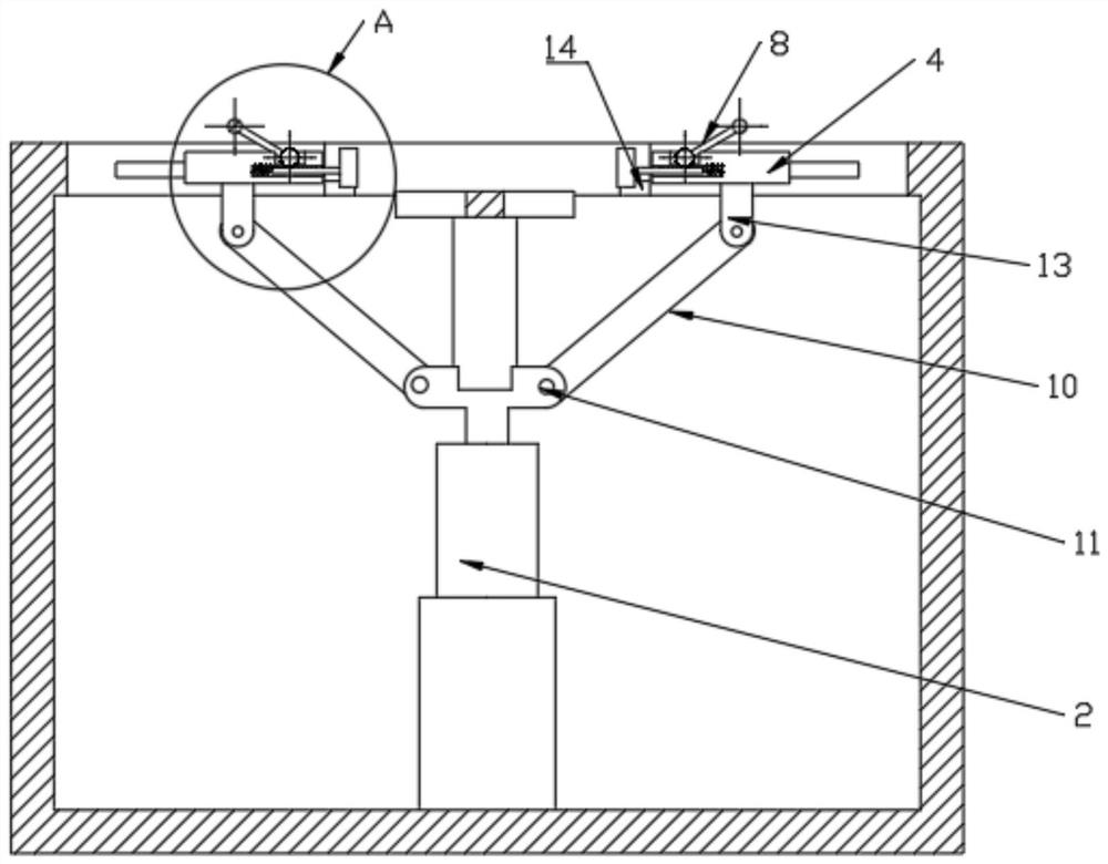
[0019] Such as Figure 1-3 As shown, it is a structural diagram of a clamping device for component processing provided by an embodiment of the present invention, including:

[0020] Workbench 1 for support and installation;

[0021] Placement groove 5 is provided on the workbench 1 for positioning and placement of components, and at least one side of the placement groove 5 is provided with a sliding groove 3;

[0022] The clamping plate 4 is slidably arranged ...


PUM


Abstract

The invention is applicable to the technical field of machining, and provides a clamping device for component machining. The clamping device is characterized by comprising a worktable, a containing groove, clamping plates, a top table and a lifting driving piece; the containing groove is formed in the worktable and used for positioning and containing components, and sliding grooves are formed in at least one side of the containing groove; the clamping plates are arranged in the sliding grooves in a sliding manner; the top table is arranged in the containing groove in the manner of being capable of ascending and descending; the lifting driving piece is fixedly connected with the top table, is rotationally connected to the bottoms of the clamping plates through connecting rods and is used for driving the top table to ascend and descend and driving the clamping plates to slide; the components are placed on the top table, the lifting driving piece drives the top table to descend and pulls the clamping plates to get close to the top table through the connecting rods, the components enter the containing groove, and the clamping plates clamp the components; and the lifting driving piece drives the top table to be lifted and pushes the clamping plates to slide away from the top table through the connecting rods, the clamping plates release the components, and the top table is lifted to eject the components out of the containing groove. The clamping device has the advantages of being simple in structure, convenient to operate, good in clamping stability and capable of saving energy.

Description

technical field [0001] The invention belongs to the technical field of mechanical processing, and in particular relates to a clamping device for component processing. Background technique [0002] With the development of science and technology and the progress of society, people's lives have been greatly improved, and the needs of life have further promoted the development of machining. Machining is the processing of parts. The parts can be metal, plastic, etc., among which metal Components are more common, and metal is a substance that has luster (that is, strongly reflects visible light), is malleable, and is easy to conduct electricity and heat. The vast majority of metal elements on the earth exist in nature in a compound state. Metal parts refer to the collective name of metal blocks, metal rods, metal tubes, etc. of various specifications and shapes made of metal materials. In the process of parts processing, clamping devices are often used. The common clamping device...

Claims


Application Information

Patent Timeline
Patent Type & Authority Applications(China)
IPC IPC(8): B25H1/16B25B11/00
CPCB25B11/00B25H1/16
Inventor 郑斗
Owner 郑斗
Why Eureka
Try Eureka