Rapid forming precision mold manufacturing welding device
A technology of precision molds and welding devices, applied in the field of mold processing, can solve the problems of small scope of application and inability to replace fixtures, and achieve the effect of improving the scope of application, protecting eyesight, and stabilizing mobile welding
- Summary
- Abstract
- Description
- Claims
- Application Information
AI Technical Summary
Problems solved by technology
Method used
Image
Examples
Embodiment 1
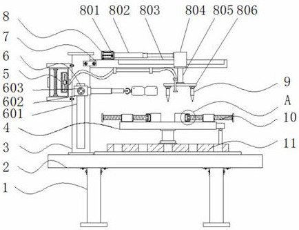
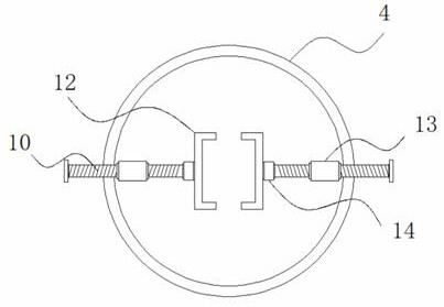
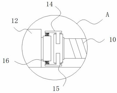
[0035] Example 1: See Figure 1-6, a rapid prototyping precision mold manufacturing welding device, including a leg 1 and a base 2, four sets of legs 1 are fixedly connected to the four corners at the bottom of the base 2, a column 3 is fixedly connected to one side of the top of the base 2, and the base 2 The top of the column 3 is provided with a workbench 4, one side of the column 3 is fixedly connected with a purification mechanism 5, one end of the column 3 is movably connected with an eye protection structure 6, and the top of the other side of the column 3 is fixedly connected with a cross bar 7, and the cross bar 7 The top end is fixedly connected with a stabilizing mechanism 8, the bottom end of the cross bar 7 is provided with two sets of laser heads 9, the top end of the base 2 is fixedly connected with an adjustment structure 11, and the top end of the workbench 4 is provided with a clamping structure;
[0036] see Figure 1-6 , a rapid prototyping precision mold ...
Embodiment 2
[0039] Embodiment 2: the purification mechanism 5 is made up of a purification box 501, a filter screen 502, an air outlet 503, a smoking pipe 504 and a negative pressure fan 505, the purification box 501 is fixedly connected to one side of the column 3, and one side of the purification box 501 is fixedly connected There is an air outlet 503, the interior of the purification box 501 is fixedly connected with a filter screen 502, and one side of the interior of the purification box 501 is fixedly connected with a negative pressure fan 505. The model of the negative pressure fan 505 is XN-1, and the other side of the purification box 501 The side is fixedly connected with a smoking pipe 504;
[0040] The input end of the negative pressure fan 505 is fixedly connected to one side of the smoking pipe 504;
[0041] Specifically, such as figure 1 and Figure 4 As shown, when the mold is welded with the laser head 9, smoke will be produced. There is a pungent smell in the smoke and...
Embodiment 3
[0042] Embodiment 3: the eye protection structure 6 is made up of the first chute 601, the first slide block 602, the adjustment bolt 603, the adjustment rod 604, the adjustment wheel 605 and the goggles 606, the first chute 601 is arranged at one end of the column 3, The inside of the first chute 601 is provided with a first slider 602, one end of the first slider 602 is movably connected with an adjustment bolt 603, one side of the first slider 602 is fixedly connected with an adjustment rod 604, and one side of the adjustment rod 604 An adjustment wheel 605 is fixedly connected, and one side of the adjustment wheel 605 is fixedly connected with goggles 606;
[0043] The width inside the first chute 601 is greater than the width outside the first slider 602, and the first slider 602 is embedded in the inside of the first chute 601;
[0044] Specifically, such as figure 1 and Figure 5 As shown, the light generated when the laser head 9 is welded is irritating and harmful t...
PUM
 Abstract
Description
Claims
Application Information
 - R&D
- Intellectual Property
- Life Sciences
- Materials
- Tech Scout
- Unparalleled Data Quality
- Higher Quality Content
- 60% Fewer Hallucinations
Browse by: Latest US Patents, China's latest patents, Technical Efficacy Thesaurus, Application Domain, Technology Topic, Popular Technical Reports.
© 2025 PatSnap. All rights reserved.Legal|Privacy policy|Modern Slavery Act Transparency Statement|Sitemap|About US| Contact US: help@patsnap.com


