Configuration structure of photo-oxygen purification equipment processing module

A technology for processing modules and configuring structures, applied in gas processing, chemical/physical processes, chemical instruments and methods, etc., can solve the problems of small resistance, less than ideal effect, weakened vortex effect, etc., to increase the walking path, increase The effect of exhaust gas flow walking path and improving mixing adequacy

Pending Publication Date: 2021-04-30
FIRST TRACTOR
View PDF14 Cites 0 Cited by
  • Summary
  • Abstract
  • Description
  • Claims
  • Application Information

AI Technical Summary

Problems solved by technology

Some UV photo-oxygen equipment is equipped with similar measures, but there are some defects. For example, the Chinese patent application number 201720078917.2 discloses a high-efficiency photo-oxygen catalytic device. Multiple guide vanes on the top of the photo-oxygen catalytic unit; the installation direction of the guide grilles in the adjacent two groups of photo-oxygen catalytic units is opposite. Although this design makes the air flow evenly mixed and improves the efficiency of photo-oxygen catalysis; but there are some problems: each phase The central position of the adjacent dispersed guide vanes is a rectangular lattice structure, the guide vanes are in the same position in each row and column, and they are clustered in the forward direction of the exhaust gas flow. In this way, (1) when the blade width is small, the small Local vortex airflow is easy to appear, but because the surrounding of the distributed blades is neutral, the resistance is relatively small, and most of the main exhaust gas flow is easier to escape from the gap between adjacent rows and columns of blades, that is, the gap around the outer periphery of the blade row. , the effect is not ideal; (2) When the width of the blade is large, when the exhaust gas flow passes through, the vortex is relatively strong only at the blade that first touches, and then the airflow in the direction of flow will be due to the blades at the same height behind The vortex effect is gradually weakened by the series of blocks, and the effect is not ideal; (3) When the width of the blade is medium, the above two problems will also exist to varying degrees, and it cannot be taken into account. After escaping and passing, part of the airflow will pass through the layer-by-layer blocking effect of the blade string in the direction of flow, and the vortex effect will gradually weaken, and the effect is not ideal.

Method used


Image

  • Configuration structure of photo-oxygen purification equipment processing module
  • Configuration structure of photo-oxygen purification equipment processing module
  • Configuration structure of photo-oxygen purification equipment processing module

Examples


Embodiment Construction

[0037] The technical solution of the present invention will be clearly and completely described below in conjunction with specific embodiments. Apparently, the described embodiments are only a part of the embodiments of the present invention, not all of them. Based on the embodiments of the present invention, all other embodiments obtained by persons of ordinary skill in the art without making creative efforts belong to the protection scope of the present invention.

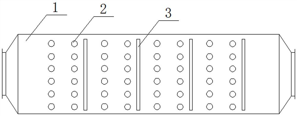
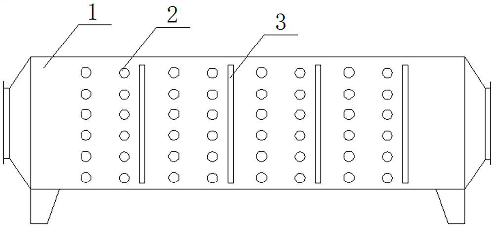
[0038] Depend on Figure 1-Figure 2 It can be seen that the center position of each adjacent four photo-oxygen lamps 2 (two photo-oxygen lamp groups in two adjacent columns) is a rectangular lattice structure. It is more common in technology.

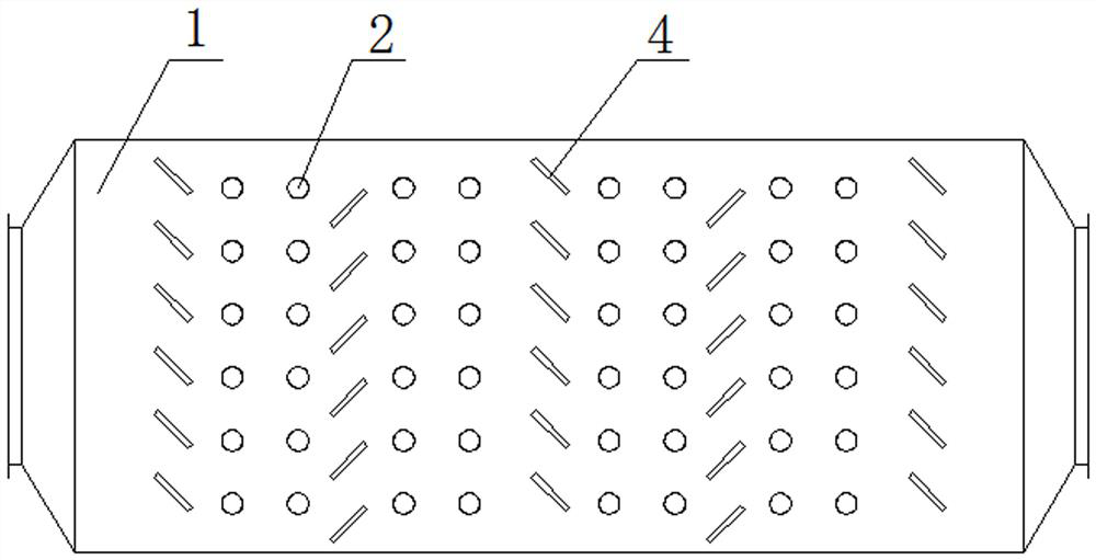
[0039] A configuration structure of photo-oxygen purification equipment processing modules, please refer to Figure 3-Figure 12 , the configuration structure of the processing module includes a box body 1, at least two rows of photooxygen lamp groups arranged in the box ...


PUM


Abstract

The invention discloses a configuration structure of a treatment module of photo-oxygen purification equipment. The configuration structure comprises a box body and at least two rows of photo-oxygen lamp sets arranged in the box body in the advancing direction of waste gas flow. The light oxygen lamps in each column of light oxygen lamp group are arranged front and back along the width direction of the box body or are arranged up and down along the height direction of the box body, and the centers of every four adjacent light oxygen lamps form a rectangular structure. The configuration structure of the treatment module further comprises N columns of flow guide plate sets from the first column to the N-th column which are arranged in the box body in the advancing direction of waste gas flow, wherein N is larger than or equal to 2; and at least two rows of guide plate groups are staggered. The guide plate groups are added and at least two columns of guide plate groups are arranged in a staggered manner, so that an exhaust gas flow walking path can be increased, the exhaust gas flow mixing sufficiency is improved, and the treatment efficiency of the photo-oxygen purification equipment is improved.

Description

technical field [0001] The invention relates to the field of waste gas treatment of photo-oxygen purification equipment, in particular to a configuration structure of treatment modules of photo-oxygen purification equipment. Background technique [0002] Photo-oxygen purification equipment can be used for the treatment of VOCs organic waste gas. The current photo-oxygen purification equipment includes a matrix of UV photo-oxygen lamps and a photocatalyst plate that is matched later. The UV photo-oxygen lamp has strong radiation, and its main function is when the waste gas passes through Crack the organic matter in the exhaust gas and decompose it into harmless carbon dioxide and water; the photocatalyst plate amplifies the effect of the light source and can improve the purification efficiency. [0003] In the current photo-oxygen purification equipment, the purification combination structure of the UV photo-oxygen lamp matrix and the subsequent matching photocatalyst plate i...

Claims


Application Information

Patent Timeline
IPC IPC(8): B01F3/02B01D53/00B01D53/86B01F23/10
CPCB01D53/007B01D53/86B01D2259/81B01D2258/02B01F23/19
Inventor 吴志刚杨启帆孙峰郭海清宋保华王冲冲刘文化郭丹丹
Owner FIRST TRACTOR
Why Eureka
Try Eureka