
Movable VOC treatment device

A processing device and mobile technology, applied in gas treatment, combustion methods, lighting and heating equipment, etc., can solve the problems of unsuitable promotion and popularization, short stay time, inconvenient movement, etc., and achieve suitable popularization and popularization. Residence time, the effect of promoting sufficient adsorption

Pending Publication Date: 2021-04-30
广东诚一环保科技有限公司
View PDF4 Cites 1 Cited by
  • Summary
  • Abstract
  • Description
  • Claims
  • Application Information

AI Technical Summary

Problems solved by technology

[0003] The VOC emitted by the VOC emission system needs to be purified before it can be discharged, so it needs to be treated by a VOC treatment device. However, the VOC treatment device in the prior art is not easy to move, especially not suitable for mobile VOC treatment of various small factories. , it is difficult to realize the purpose of going where there is VOC waste gas that needs to be treated, which makes the cost of small factories to deal with waste gas containing VOC remain high, which is not conducive to the development of environmental protection, and is not suitable for promotion and popularization; in addition, the existing technology It is difficult for the VOC treatment device to effectively decelerate the exhaust gas to be treated, so that the exhaust gas stays in the desorption bed for a short time, making it difficult for the volatile organic compounds in the exhaust gas to be fully adsorbed by the adsorption filter element, which in turn makes it difficult for the volatile organic compounds. The purification effect is not very good

Method used


Image

  • Movable VOC treatment device
  • Movable VOC treatment device
  • Movable VOC treatment device

Examples


Embodiment Construction

[0025] The following will clearly and completely describe the technical solutions in the embodiments of the present invention with reference to the accompanying drawings in the embodiments of the present invention. Obviously, the described embodiments are only some, not all, embodiments of the present invention. Based on the embodiments of the present invention, all other embodiments obtained by persons of ordinary skill in the art without making creative efforts belong to the protection scope of the present invention.

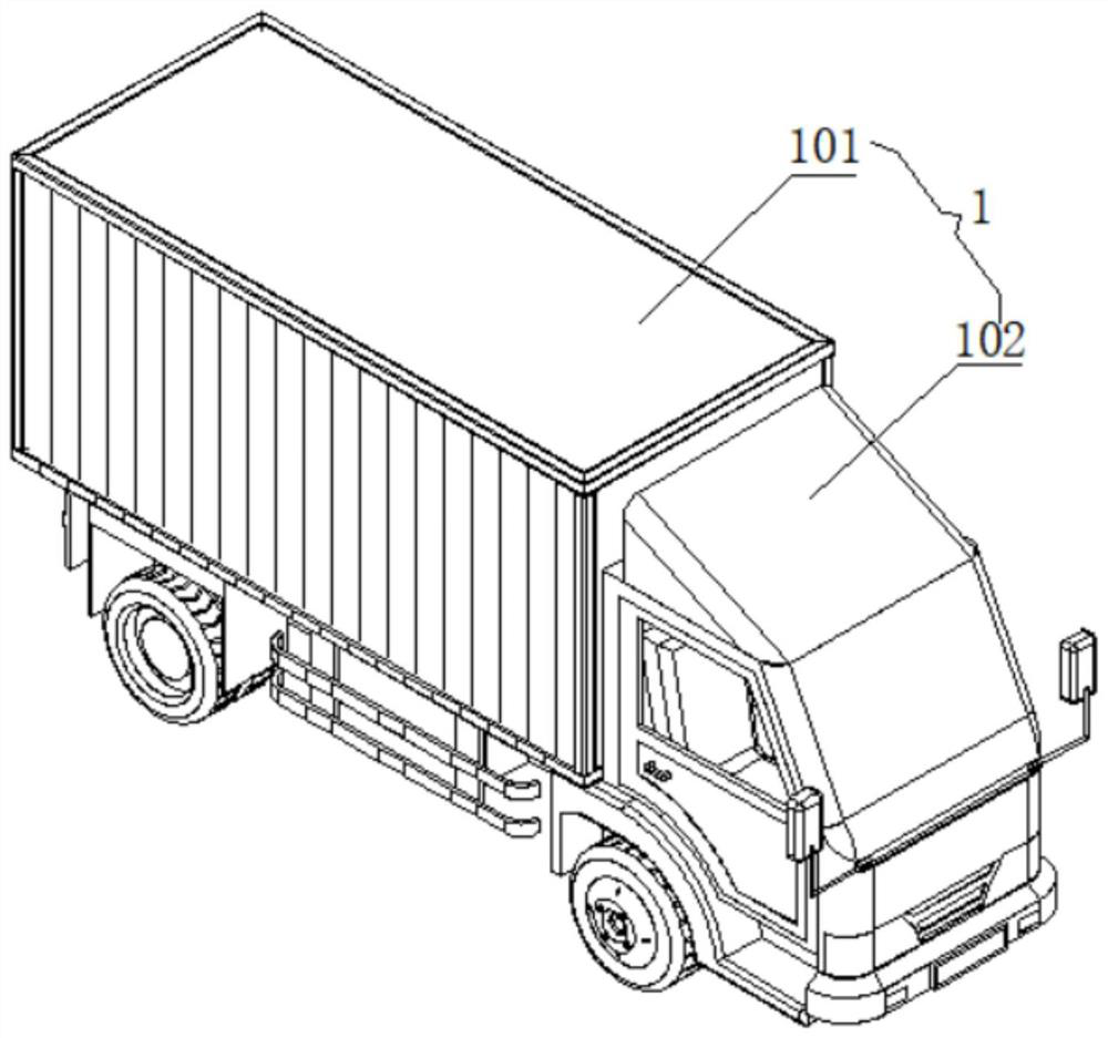
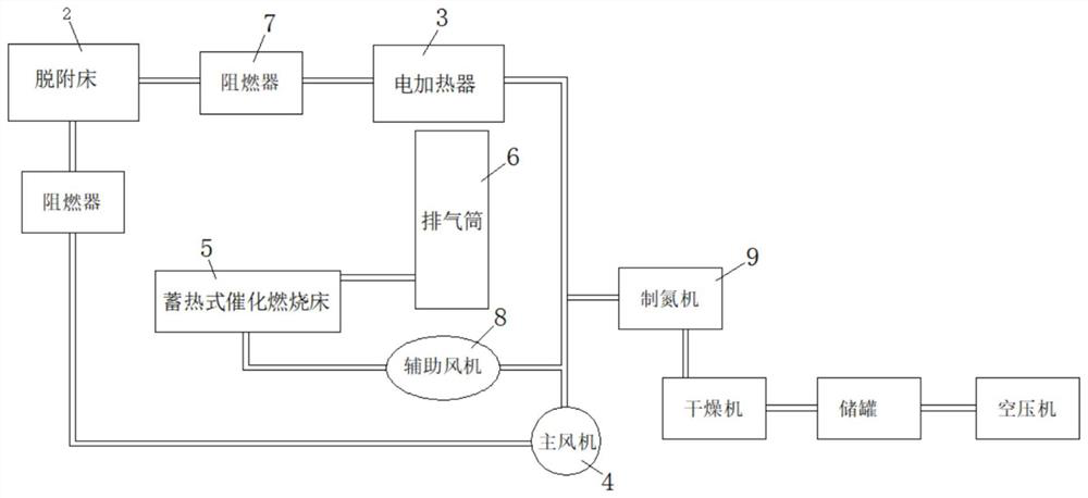
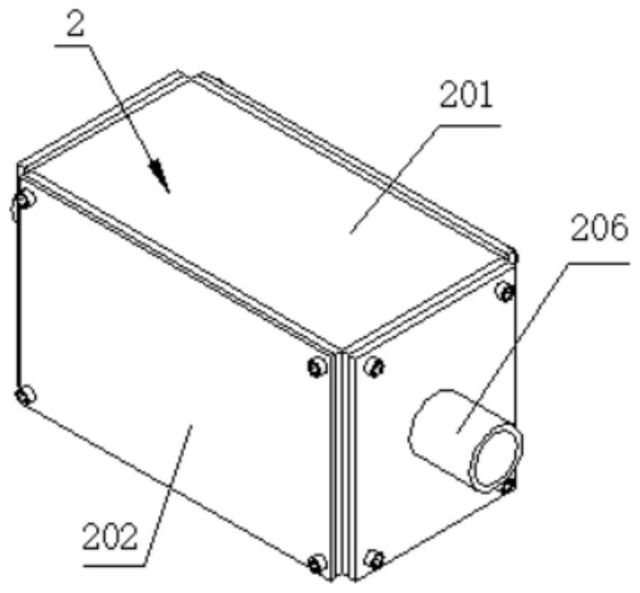
[0026] see Figure 1-7 As shown, the present invention provides a mobile VOC treatment device. A mobile mechanism 1 is formed by a car body 102 and a compartment 101 thereon. The hot nitrogen cycle desorption regeneration system of the device is arranged in the compartment 101, and the hot nitrogen cycle The desorption regeneration system includes an electric heater 3, a desorption bed 2 and a main fan 4 connected in sequence, and a pipeline is drawn from the ...


PUM


Abstract

The invention discloses a mobile VOC treatment device. A mobile mechanism is formed by a vehicle body and a carriage on the vehicle body, a hot nitrogen cyclic desorption regeneration system of the device is arranged in the carriage, the hot nitrogen cyclic desorption regeneration system comprises an electric heater, a desorption bed and a main fan which are connected in sequence, a pipeline is led out of the air outlet end of the main fan to be connected with a heat accumulating type catalytic combustion bed, the heat accumulating type catalytic combustion bed is connected with an exhaust funnel, the output end of a nitrogen making machine is connected to the pipeline between the main fan and the electric heater, flame retardants are arranged between the desorption bed and the electric heater and between the desorption bed and the main fan, and the air outlet end of an auxiliary fan is connected between the heat accumulating type catalytic combustion bed and the pipeline of the main fan to supplement air for the heat accumulating type catalytic combustion bed. The hot nitrogen cyclic desorption regeneration system is integrated in the carriage on the vehicle body, so that the system is convenient and flexible to use, VOC waste gas of each factory can be conveniently treated in a flowing manner, and the desorption process of an adsorbent is realized.

Description

technical field [0001] The invention relates to the technical field of VOC processing, in particular to a mobile VOC processing device. Background technique [0002] VOC is the English abbreviation of volatile organic compounds (volatile organic compounds). VOC in the general sense is command volatile organic compounds; but the definition in the sense of environmental protection refers to a type of active volatile organic compounds, that is, the type of volatile organic compounds that will cause harm. VOC stands for Volatile Organic Compounds, which have a huge impact on human health. When the VOC in the room reaches a certain concentration, people will feel headache, nausea, vomiting, fatigue, etc. in a short time. decline and other serious consequences. [0003] The VOC emitted by the VOC emission system needs to be purified before it can be discharged, so it needs to be treated by a VOC treatment device. However, the VOC treatment device in the prior art is not easy to...

Claims


Application Information

Patent Timeline
Patent Type & Authority Applications(China)
IPC IPC(8): B01D53/04F23G7/07
CPCB01D53/04F23G7/07B01D53/0446B01D2257/708B01D2259/40083B01D2259/455
Inventor 杨乐能何宏亮朱国平何敬苏黄荣鑫
Owner 广东诚一环保科技有限公司
Learn More