
Angle-adjustable lens base

A lens holder and lens technology, applied in installation, optics, instruments, etc., can solve the problems of complex support structure, poor rigidity, high cost, etc., and achieve the effect of simple operation, low cost, and good rigidity

Inactive Publication Date: 2021-04-27
哈尔滨和达光电仪器技术开发有限公司
View PDF6 Cites 0 Cited by
  • Summary
  • Abstract
  • Description
  • Claims
  • Application Information

AI Technical Summary

Problems solved by technology

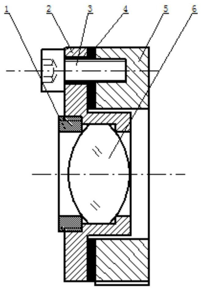
[0003] The present invention aims to solve the problems of complex support structure, poor rigidity and high cost in the prior art when fine-tuning the angle of the lens, and further provides an angle-adjustable lens base

Method used


Image

  • Angle-adjustable lens base

Examples


specific Embodiment approach 1

[0012]DETAILED DESCRIPTION One: Combinationfigure 1In the present embodiment, an angularly adjustable lens base includes a lens compression ring 1, a lens seat 2, and a base 5, wherein the mounting base 5 is fixed on an optical platform, and the mounting base 5 is opened. The through hole is mounted, and the lens seat 2 has a "convex" glyph structure and there is a three-stage step through hole thereof, and the lens seat 2 is fixed to the mounting base 5 and secured between the mounting base 5. , There is a regulating spacer 4 between the shoulder surface of the lens seat 2 and the end face of the mounting base 5, and the lens 6 is mounted in the middle of the three-stage step through hole and one end surface is passed through the lens pressure in the three-stage step through the surface. Circle 1 fixed position. The three-stage step through hole is from left to right to one-stage through hole. The lens 6 is fitted within the secondary through hole, and both ends of the lens 6 are r...


PUM


Abstract

The invention discloses an angle-adjustable lens base, and belongs to the technical field of optical equipment. The problems that in the prior art, when angle fine adjustment is conducted on a lens, an adopted supporting structure is complex, rigidity is poor, and cost is high are solved. The lens base comprises a lens pressing ring, a lens seat and an installation base, the installation base is fixedly installed on an optical platform, an installation through hole is formed in the installation base, the lens seat is of an inverted-T-shaped structure, a three-level step through hole is formed in the lens seat, and the lens seat is clamped on the installation base and fixedly connected with the installation base through a compression screw. An adjusting gasket is installed between the shoulder face of the lens seat and the end face of the installation base, the lens is installed in the middle of the three-level step through hole, and the curved face of one end of the lens is fixed through the lens pressing ring clamped in the three-level step through hole. Compared with the prior art, the lens base is simpler in structure, better in rigidity, lower in cost and simpler to operate.

Description

Technical field[0001]The present invention relates to an angularly adjustable lens base, belonging to the technical field of optical equipment.Background technique[0002]When performing high-precision optical impairment, the lens used is required to be fine-tuned. In the prior art, the lens support structure used in the optical impairment is complicated, the operation is high, the stiffness is poor, and the production cost is high.Inventive content[0003]The present invention is to solve the problem of complex, stiffness and high cost of the support structure, high in the prior art, and high, and therefore provide an angularly adjustable lens base.[0004]The present invention is to solve the technical solution used by the above technical problems:[0005]An angle-adjustable lens base comprising a lens aircraft, lens seat, and mounting base, wherein the mounting base is fixed to an optical platform, and an mounting base is opened, and the lens is present. The convex "glyph structure and t...

Claims


Application Information

Patent Timeline
Patent Type & Authority Applications(China)
IPC IPC(8): G02B7/02
CPCG02B7/023G02B7/022
Inventor 张恩侨
Owner 哈尔滨和达光电仪器技术开发有限公司
Learn More