
Novel electronic brake power assisting device

A technology of booster device and electronic braking, applied in the direction of brake transmission, brake, transportation and packaging, etc., can solve the problems of providing brake booster device, braking, and inability to meet different driving habits according to the needs of different customers.

Pending Publication Date: 2021-04-27
HOZON NEW ENERGY AUTOMOBILE CO LTD
View PDF0 Cites 0 Cited by
  • Summary
  • Abstract
  • Description
  • Claims
  • Application Information

AI Technical Summary

Problems solved by technology

[0003] At present, there is only one brake assist curve for vehicles in the market, which cannot satisfy customers with different driving habits. For example, some female customers have relatively small power, and under the same power assist curve, they need to use a lot of force to achieve it, while male customers have stronger strength. Large, when the pedal is stepped on slightly, the brake will appear completely. At present, there is no adjustable brake booster device on the market to meet the needs of different customers.

Method used


Image

  • Novel electronic brake power assisting device
  • Novel electronic brake power assisting device
  • Novel electronic brake power assisting device

Examples


Embodiment Construction

[0019] The following will clearly and completely describe the technical solutions in the embodiments of the present invention with reference to the accompanying drawings in the embodiments of the present invention. Obviously, the described embodiments are only some, not all, embodiments of the present invention. Based on the embodiments of the present invention, all other embodiments obtained by persons of ordinary skill in the art without making creative efforts belong to the protection scope of the present invention.

[0020] In the description of the present invention, it should be noted that the terms "center", "upper", "lower", "left", "right", "vertical", "horizontal", "inner", "outer" etc. The indicated orientation or positional relationship is based on the orientation or positional relationship shown in the drawings, and is only for the convenience of describing the present invention and simplifying the description, rather than indicating or implying that the referred d...


PUM


Abstract

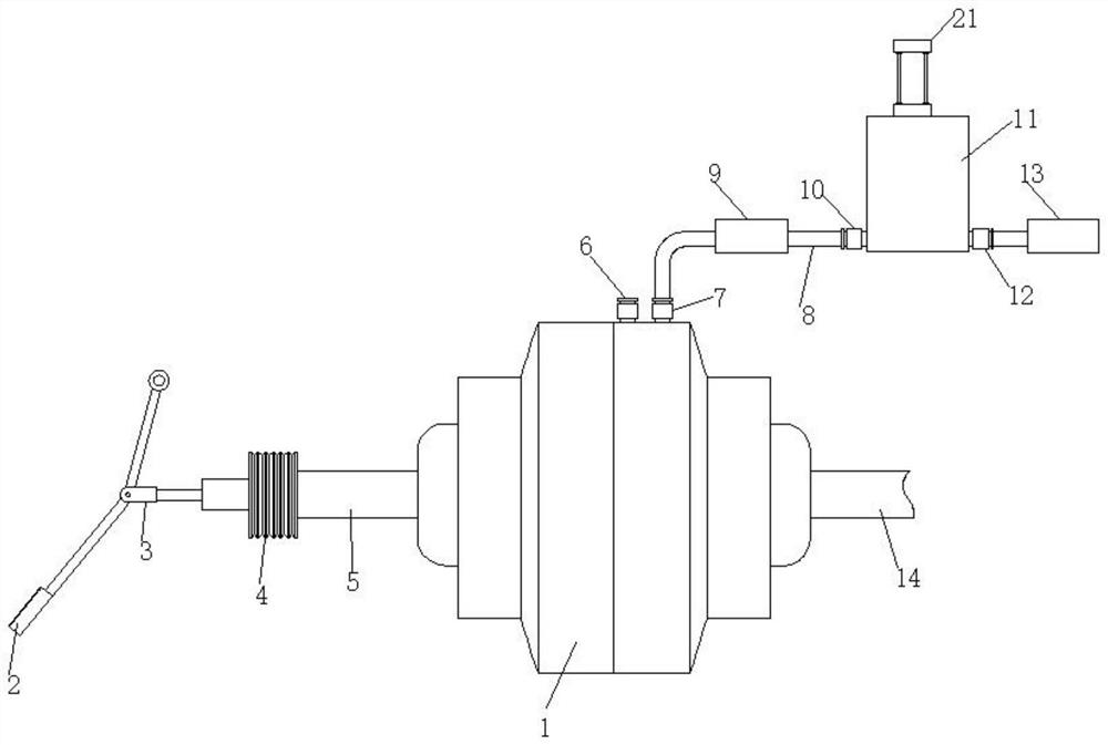
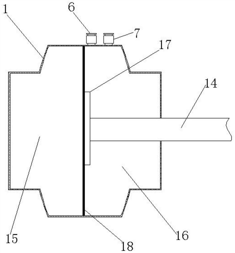
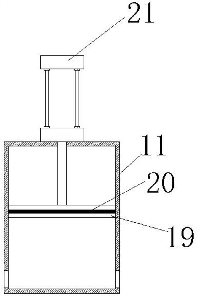
The invention discloses a novel electronic brake power assisting device which comprises a power assisting device shell, a first cavity and a second cavity are formed in the power assisting device shell, a power assisting valve is fixedly connected to the left side of the power assisting device shell, and a pedal connecting rod is slidably connected to the end, away from the power assisting device shell, of the power assisting valve. A dust cover is arranged between the pedal connecting rod and the power assisting valve, and the end, away from the power assisting valve, of the pedal connecting rod is rotationally connected with a brake foot. According to the invention, an electric push rod is electrically connected with an electronic stabilization system and a central control screen, and the strength of the assistance force is adjusted through the central control screen, so that the extension length of the extension shaft of the electric push rod is adjusted. And the volume in the adjusting tank is further adjusted, and certain air is automatically supplemented to the second cavity when the vacuum system works, so that the pressure difference between the first cavity and the second cavity is adjusted, the thrust of the diaphragm to the push plate and the hydraulic power-assisted push rod is adjusted, and power-assisted curve adjustment is achieved.

Description

technical field [0001] The invention relates to the technical field of automobiles, in particular to a novel electronic brake booster device. Background technique [0002] Hydraulic brake boosting is an enhanced function that is supported by electronic stability control elements within the vehicle's braking system in conjunction with conventional vacuum brake boosters and master cylinders. When the braking force is high, increase the brake pedal effect. [0003] At present, there is only one brake assist curve for vehicles in the market, which cannot satisfy customers with different driving habits. For example, some female customers have relatively small power, and under the same power assist curve, they need to use a lot of force to achieve it, while male customers have stronger strength. It is too big, and the brakes will be completely braked when the pedal is slightly stepped on. At present, there is no adjustable brake booster device on the market to meet the needs of d...

Claims


Application Information

Patent Timeline
IPC IPC(8): B60T13/72
CPCB60T13/72
Inventor 王海源
Owner HOZON NEW ENERGY AUTOMOBILE CO LTD
Learn More