Mechanical seal following floating

A technology of mechanical seals and seals, which is applied in the field of follow-up floating mechanical seals, can solve the problems of large radial and axial fluctuations between the shell and the shaft, oil leakage, etc., and achieve reliable sealing effects

Pending Publication Date: 2020-10-09
潍坊晨昊机械有限公司
View PDF0 Cites 0 Cited by
  • Summary
  • Abstract
  • Description
  • Claims
  • Application Information

AI Technical Summary

Problems solved by technology

[0006] The technical solution of the present invention is to provide a follow-up floating mechanical seal, which solves the problem of oil leakage between the casing (cylinder) and the shaft due to the large load-bearing load of the existing mechanical reducer or drum. question

Method used


Image

  • Mechanical seal following floating

Examples


Embodiment Construction

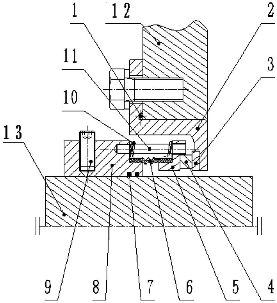
[0018] In order to further disclose the technical solutions of the present invention, the following will be described in detail in conjunction with the accompanying drawings of the description:

[0019] The invention includes: fixed seat A (2), end face seal D (3), seal (1) of fixed seat A, end face seal B (5), end face seal E (4) seat C, fixed seat C (8), the axial seal F (7), the rubber sleeve (6), the set screw (9), the spring (10) and the guide shaft (11), the seal (1) of the fixed seat A (2) ) is sandwiched between the shell (or barrel 12) and the fixing seat A (2), the fixing seat A is fixed on the shell or barrel by bolts, and the fixing seat C (8) is fixed on the On the shaft (13), the guide shaft is installed on the outside of the annular groove formed by the fixed seat C (8) and the end face seal seat B (5), and one end is fixed on the fixed seat C (8) by threads, and the spring (10) sets On the guide shaft (11), the other end of the guide shaft is inserted into the...


PUM


Abstract

The invention discloses a mechanical seal following floating. The mechanical seal comprises a fixed seat A, an end face sealing part D, a sealing part of the fixed seat A, an end face sealing seat B,an end face sealing part E inlaid on the end face sealing seat B in a sealed mode, a fixed seat C, an axial sealing part F of the fixed seat C, a rubber sleeve, a spring and a guiding shaft; the sealing part of the fixed seat A is clamped between a shell and the fixed seat A, the fixed seat A is fixed to the shell through a bolt, and the fixed seat C is fixed to a shaft through a set screw; the guiding shaft is mounted on the outer sides of the two sides of a groove formed by the fixed seat C and the end face sealing seat B, one end of the guiding shaft is fixed to the fixed seat C, the springsleeves the guiding shaft, the other end of the guiding shaft is inserted into a hole of the end face sealing seat B, and the end face sealing part D and the end face sealing part E are mounted between the fixed seat A and the end face sealing seat B; and the rubber sleeve is mounted on the inner side of the groove, one end of the rubber sleeve is mounted on the fixed seat C, the other end of therubber sleeve is mounted on the end face sealing seat B, the axial sealing part F is mounted between the fixed seat C and the shaft, and thus the mechanical seal following floating is constituted.

Description

technical field [0001] The invention relates to a kind of working condition mechanical reducer or roller due to the large load-carrying load, which causes oil leakage between the shell and the shaft in the radial and axial directions, and then solves the problem of oil leakage with a floating mechanical seal, especially for rollers or rollers. The output shaft of the reducer bears a large torque, which causes the floating mechanical seal to follow the large clearance of the shaft and the bearing. Background technique [0002] The seal is a necessary part for the reducer to seal, lubricate and change oil in the transmission equipment under working conditions. The seal between the existing reducer (or drum) shell (cylinder) and the shaft is a skeleton seal or a mechanical dynamic seal. Relative rotation requires that the lip of the skeleton oil seal be coaxial with the shaft of the reducer (or pulley) to ensure good sealing. The reducer (or pulley) is often operated for a long...

Claims


Application Information

Patent Timeline
Patent Type & Authority Applications(China)
IPC IPC(8): F16J15/34F16H57/029
CPCF16H57/029F16J15/3452F16J15/3464
Inventor 宋玉科荣雁尹赐禹王召柏
Owner 潍坊晨昊机械有限公司
Why Eureka
Try Eureka