PCB receiving machine push rod with adjustable thrust

A technology of PCB board and board receiving machine, which is applied in the direction of stacking receiving device, electrical components, and printed circuit manufacturing. Board, improve labor productivity, low cost of transformation effect

Inactive Publication Date: 2012-11-07
张朝林
View PDF0 Cites 0 Cited by
  • Summary
  • Abstract
  • Description
  • Claims
  • Application Information

AI Technical Summary

Problems solved by technology

[0002] At present, on the PCB board production line, the push rod involved in the board receiving machine (also known as the board pushing machine) to push the PCB board to move into the board receiving frame has a large and constant thrust, but due to the Between the conveyor and the conveying track, it is often due to various reasons such as the deviation of the position of the receiving frame, or the deformation of the frame after long-term use, etc., which often leads to unsmooth flow of the plate, and even causes cardboard jamming
At this time, if the thrust is fixed again, the hard push will inevitably cause the PCB board to be broken, damaged and scrapped, or even the receiving frame will be damaged.
Therefore, when a card board failure occurs, the thrust of the push rod must be automatically reduced accordingly, otherwise it will not only affect the production efficiency of the PCB board production line, but also cause greater economic losses

Method used


Image

  • PCB receiving machine push rod with adjustable thrust
  • PCB receiving machine push rod with adjustable thrust

Examples


Embodiment Construction

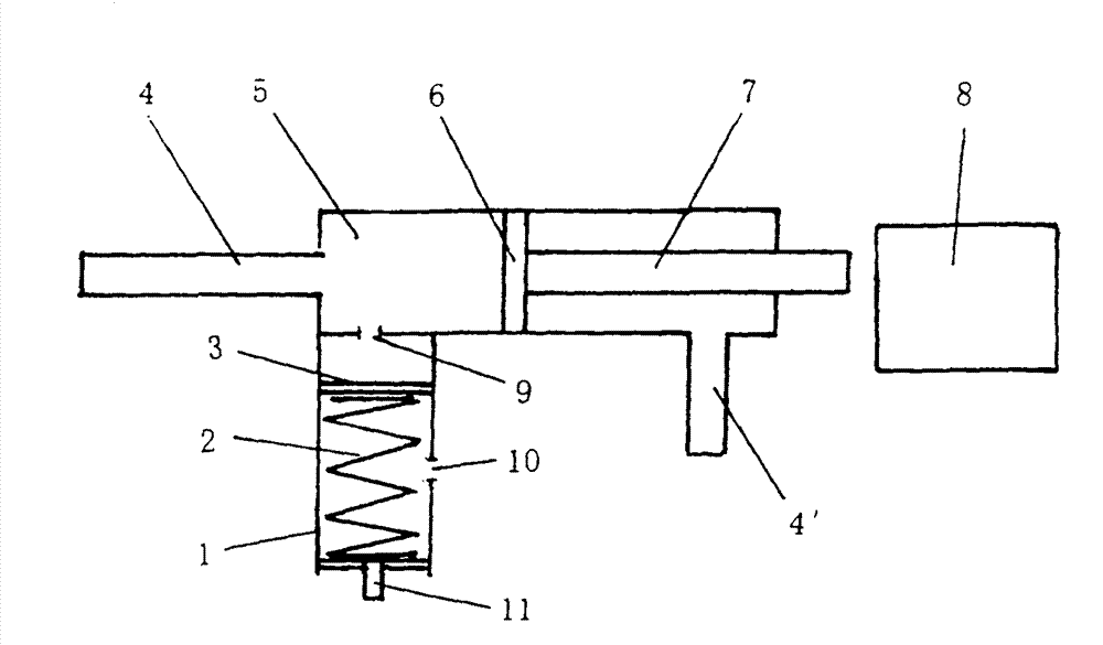
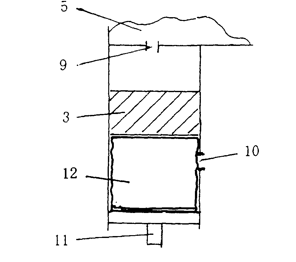
[0014] Such as figure 1 and figure 2 It can be seen from the structural schematic diagram that an adjustable thrust push rod of a PCB board receiving machine includes a cylinder 5, an air supply pipe 4 and an air supply pipe 4', and a push rod 7 connected to the piston 6 placed in the cylinder 5, which is characterized in that : The cylinder 5 is connected to the pressure controller 1, and the gas path is communicated through the air hole 9, the pressure controller 1 has a built-in second piston 3, and the second piston 3 is connected to the bottom of the pressure controller 1 The wall of the pressure controller 1 is provided with an exhaust hole 10 .

[0015] A pressure regulating knob 11 is arranged at the bottom of the pressure controller 1 .

[0016] A spring 2 is placed between the second piston 3 and the pressure regulating knob 11 .

[0017] Or the second piston 3 and the bottom of the pressure controller 1 are provided with magnetic steel or magnetic force coils fa...


PUM


Abstract

The invention relates to a PCB receiving machine push rod with adjustable thrust, comprising an air cylinder, an air supply pipe and a push rod connected with a piston arranged in the air cylinder. The push rod is characterized in that the air cylinder is connected with a pressure controller and realizes air path communication through vent holes; the pressure controller is internally provided with a second piston, and the wall of the pressure controller between the second piston and the bottom of the pressure controller is provided with vent holes; the bottom of the pressure controller is provided with a pressure regulation knob, and a spring, or a compressible aeration air bag or homopolar magnetic steel in opposite directions or magnetic coils are arranged between the second piston and the pressure regulation knob; and the pressure regulation knob can be used for regulating the upward thrust of the second piston according to the maximum safety working pressure of the push rod. The invention has the advantages of simple structure, low equipment reformation cost and convenient use. On the traditional equipment, only one pressure controller is connected in a mode of air path communication, a small quantity of parts such as the pressure regulation knob, the second piston, and the like are added, and then the purposes for regulating and controlling the thrust of the push rod, avoiding board jam and improving the labor productivity can be achieved.

Description

technical field [0001] The invention relates to the technical field of printed circuit board (PCB board) production, in particular to a push rod whose thrust of a PCB board receiving machine can be adjusted and controlled. Background technique [0002] At present, on the PCB board production line, the push rod involved in the board receiving machine (also known as the board pushing machine) to push the PCB board to move into the board receiving frame has a large and constant thrust, but due to the Between the delivery track and the position of the receiving frame, it is often caused by various reasons such as the deviation of the position of the receiving frame, or the deformation of the frame due to long-term use, which often leads to unsmooth flow of the plate, and even causes cardboard jamming. At this time, if the thrust is fixed, hard pushing will inevitably cause the PCB board to be broken, damaged and scrapped, or even the receiving frame will be damaged. Therefore, ...

Claims


Application Information

Patent Timeline
Patent Type & Authority Patents(China)
IPC IPC(8): B65H31/00H05K3/00
Inventor 张朝林
Owner 张朝林
Why Eureka
Try Eureka