
Extraction frame with multiple groups of independent parallel functions

An extraction and functional technology, applied in the field of extraction racks, which can solve the problems of being susceptible to interference, inconvenient application, restricted structure, etc.

Inactive Publication Date: 2021-04-27
崔星海
View PDF13 Cites 0 Cited by
  • Summary
  • Abstract
  • Description
  • Claims
  • Application Information

AI Technical Summary

Problems solved by technology

However, the existing extraction racks are limited by the simple structure, so that the existing extraction work can only be completed on one extraction rack, and the utilization rate is low; and even if some extraction racks can perform two or more extraction tasks at the same time, However, they are easily interfered with each other, resulting in unqualified extraction quality and inconvenient application.

Method used


Image

  • Extraction frame with multiple groups of independent parallel functions
  • Extraction frame with multiple groups of independent parallel functions
  • Extraction frame with multiple groups of independent parallel functions

Examples


Embodiment 1

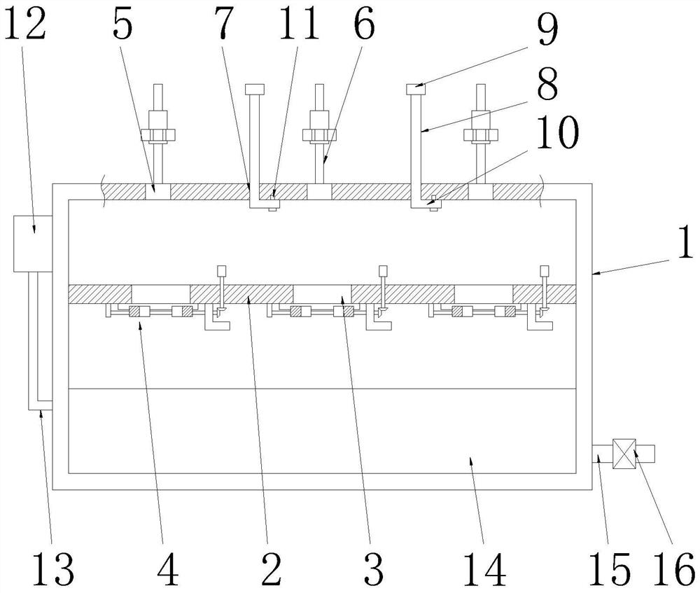
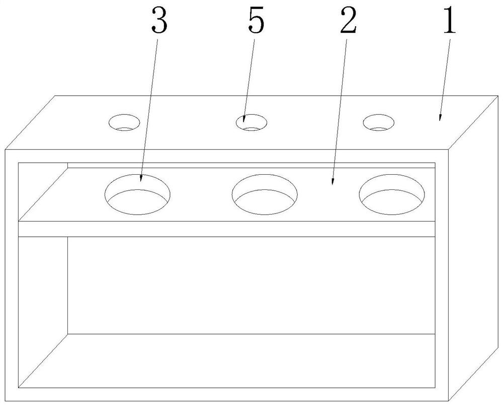
[0030] See Figure 1-2 , an extraction frame with multiple groups and independent parallel functions, comprising a seat frame 1, the seat frame 1 is a rectangular ring frame structure, the inner cavity of the seat frame 1 is provided with a supporting plate 2, and the uniform There are several supporting holes 3, and the bottom end of the supporting plate 2 is fixedly connected with a supporting clamp mechanism 4 matching with the supporting holes 3. hole 5, there is a one-to-one relationship between the drip hole 5 and the support hole 3, and the top of the mount 1 is evenly provided with a number of extraction racks 6 that match the drip hole 5, and the extraction rack There is a one-to-one correspondence relationship between 6 and the drip holes 5, and a number of partition holes 7 are evenly provided on the top wall of the mount 1, and the partition holes 7 and the drip holes 5 are interlacedly distributed. A partition 8 is slidably connected in the partition hole 7, and ...

Embodiment 2

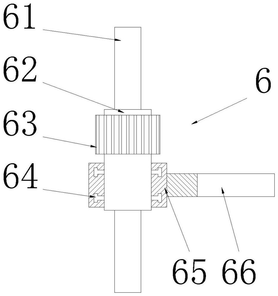
[0033] See image 3 The difference from Example 1 is that the extraction frame 6 includes a column 61, the column 61 is fixedly connected to the top of the seat frame 1, the column 61 is arranged on the rear side of the drip hole 5, and the threaded sleeve on the column 61 is provided with Lifting tube 62, the axis of the column 61 coincides with the axis of the lifting tube 62, and the outer side of the lifting tube 62 is provided with a rotary sleeve 63 and two slide rails 64, and the rotary sleeve 63 is arranged on all the slide rails 64 Above, the axis of the rotating sleeve 63 coincides with the axis of the lifting cylinder 62. The rotating sleeve 63 is made of rubber material. The slide rail 64 is a circular structure, and the slide rail 64 is a T-shaped slide rail. An angle cylinder 65 is slidably connected to the rail 64, the axis of the angle cylinder 65 coincides with the axis of the lifting cylinder 62, and the side end of the angle cylinder 65 is fixedly connected ...

Embodiment 3

[0035] See Figure 4 The difference from Embodiment 1 is that the bracket mechanism 4 includes a transmission rod 47 and two guide rails 41, the guide rails 41 are in a T-shaped structure, and the two guide rails 41 are symmetrically arranged on the bottom of the bracket hole 3. Front and rear sides, lead screw 43 is arranged between two described guide rails 41, and described lead screw 43 is arranged on the rear side of support hole 3, and one end of lead screw 43 is connected on the supporting plate 2 by bearing seat 44 rotation, and screw The other end of the bar 43 runs through the transmission frame 42 and is fixedly connected to the driven gear 45. The lead screw 43 is rotatably connected to the transmission frame 42. The transmission frame 42 is an L-shaped structure, and the transmission frame 42 is fixedly connected to the bottom end of the supporting plate 2. , the transmission rod 47 is embedded on the supporting plate 2, the transmission rod 47 is rotatably connec...


PUM


Abstract

The invention discloses an extraction frame with multiple groups of independent parallel functions. The extraction frame comprises a seat frame, a supporting plate is arranged in an inner cavity of the seat frame, a plurality of supporting holes are evenly formed in the supporting plate, a supporting and clamping mechanism is fixedly connected to the bottom end of the supporting plate, a plurality of liquid dropping holes are evenly formed in the top wall of the seat frame, a plurality of extraction frames matched with the liquid dropping holes are evenly arranged at the top end of the seat frame, a plurality of partition holes are evenly formed in the top wall of the seat frame, partition plates are slidably connected into the partition holes, and lifting plates matched with the partition holes are fixedly connected to the top ends of the partition plates. The partition plates are lifted by the lifting plates, and the limiting plates are fixed on the top wall of the inner cavity of the seat frame by positioning pins, so that the partition plates can be fixed, and two adjacent extraction frames are separated by the partition plates, so that extraction equipment is simultaneously mounted on the two extraction frames, extraction work is completed, simultaneous independent operation of a plurality of pieces of extraction equipment is ensured, the extraction quality is ensured, and the application convenience of the whole device can be greatly improved.

Description

technical field [0001] The invention relates to the technical field of extraction racks, in particular to an extraction rack with multiple sets of independent parallel functions. Background technique [0002] Extraction, also known as solvent extraction or liquid-liquid extraction, also known as extraction, is a unit operation that uses the different solubility of the components in the system to separate the mixture. That is, it is a method of transferring a solute substance from one solvent to another by using the difference in solubility or partition coefficient of the substance in two immiscible (or slightly soluble) solvents. [0003] During the extraction process, the extraction rack is needed to ensure the smooth progress of the extraction work. However, the existing extraction racks are limited by the simple structure, so that the existing extraction work can only be completed on one extraction rack, and the utilization rate is low; and even if some extraction racks ...

Claims


Application Information

Patent Timeline
Patent Type & Authority Applications(China)
IPC IPC(8): B01L9/00B01D11/00
CPCB01D11/00B01L9/00
Inventor 崔星海
Owner 崔星海
Learn More