Switching buck type LED constant-current control circuit, system and method
A technology of constant current control circuit and LED circuit, applied in the direction of energy-saving control technology, electrical components, etc., can solve the problem of low output current accuracy of LED control loop, and achieve small LED output current, good load regulation rate, good linear regulation rate Effect
- Summary
- Abstract
- Description
- Claims
- Application Information
AI Technical Summary
Problems solved by technology
Method used
Image
Examples
Embodiment 1
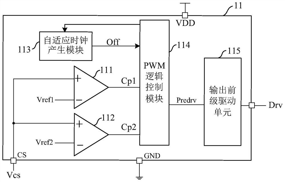
[0088] Such as image 3 As shown, this embodiment provides a switch step-down LED constant current control circuit 11, and the switch step-down LED constant current control circuit 11 includes:
[0089] An average current comparison module 111 , a peak current comparison module 112 , an adaptive clock generation module 113 , a PWM logic control module 114 and a driving module 115 .
[0090] Such as image 3 As shown, the average current comparison module 111 receives the current detection sampling signal Vcs of the step-down LED circuit, and is used to compare the current detection sampling signal Vcs with the average reference Vref1 and obtain a first comparison result Cp1.
[0091] Specifically, in this embodiment, the non-inverting input terminal of the average current comparison module 111 is connected to the current detection sampling signal Vcs, and the inverting input terminal is connected to the average reference Vref1; when the current detection sampling signal Vcs i...
Embodiment 2
[0106] like Figure 7As shown, this embodiment provides a switching step-down LED constant current control circuit 11, and the difference from Embodiment 1 is that this embodiment also adds other functional modules.
[0107] As an implementation of the present invention, the switching step-down LED constant current control circuit 11 further includes a short circuit protection module 116 . The short circuit protection module 116 receives the current detection sampling signal Vcs, compares the current detection sampling signal Vcs with the short circuit protection reference Vref3, and outputs a short circuit protection signal Short. When the current detection sampling signal Vcs is greater than the short-circuit protection reference Vref3, the power switch is turned off, wherein the short-circuit protection reference Vref3 is greater than the peak reference Vref2. In this embodiment, the non-inverting input terminal of the short-circuit protection module 116 is connected to th...
Embodiment 3
[0110] like Figure 8 As shown, this embodiment provides a switch step-down LED constant current control system 1, the switch step-down LED constant current control system 1 includes: a switch step-down LED constant current control circuit 11 and a step-down LED circuit 12.
[0111] like Figure 8 As shown, the switching step-down LED constant current control circuit 11 receives the current detection sampling signal of the step-down LED circuit 12, and outputs the driving signal of the step-down LED circuit.
[0112] Specifically, the circuit structure and working principle of the switching step-down LED constant current control circuit 11 are the same as those of the switching step-down LED constant current control circuit in Embodiment 1 or Embodiment 2, and will not be repeated here.
[0113] like Figure 8 As shown, the step-down LED circuit 12 obtains a stable output based on the control of the switching step-down LED constant current control circuit 11 .
[0114] Spe...
PUM
 Abstract
Description
Claims
Application Information
 - R&D Engineer
- R&D Manager
- IP Professional
- Industry Leading Data Capabilities
- Powerful AI technology
- Patent DNA Extraction
Browse by: Latest US Patents, China's latest patents, Technical Efficacy Thesaurus, Application Domain, Technology Topic, Popular Technical Reports.
© 2024 PatSnap. All rights reserved.Legal|Privacy policy|Modern Slavery Act Transparency Statement|Sitemap|About US| Contact US: help@patsnap.com


