Motor rotor shaft sleeve press-in machine

A technology for motor rotor shaft and motor rotor, which is applied in the direction of manufacturing stator/rotor body, etc., can solve problems such as low production efficiency, inability to ensure that the shaft sleeve is in place, and inability to meet the simultaneous pressing of two shafts, and achieve the effect of improving production efficiency.

Active Publication Date: 2021-04-23
HANGZHOU WEIGUANG ELECTRONICS
View PDF3 Cites 0 Cited by
  • Summary
  • Abstract
  • Description
  • Claims
  • Application Information

AI Technical Summary

Problems solved by technology

[0003] The invention solves the problems of the prior art that using the bush clamp to press the bush can not ensure that the bush is in place and is only suitable for pressing one shaft, which cannot meet the simultaneous pressing of two shafts, and the problem of low production efficiency, and proposes a motor rotor shaft The sleeve pressing machine divides the sleeve pressing process into two steps, namely inserting and pressing, instead of using the sleeve clamp to directly press the sleeve to ensure that the sleeve sleeve is in place, and can simultaneously press the two shafts of the motor rotor. Simultaneous pressing to improve production efficiency

Method used


Image

  • Motor rotor shaft sleeve press-in machine
  • Motor rotor shaft sleeve press-in machine
  • Motor rotor shaft sleeve press-in machine

Examples


Embodiment

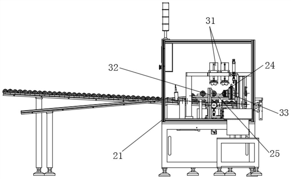
[0026] This embodiment proposes a motor rotor sleeve pressing machine, refer to figure 1 , including frame 21, motor rotor positioning block 24 is fixed on the frame 21, the two sides of motor rotor positioning block 24 are symmetrically provided with bushing inserting device 33 and bushing pressing device 32, motor rotor positioning block 24 is provided with motor The rotor pressing block 31, the motor rotor pressing block 31 is used to compress the motor rotor positioned on the motor rotor positioning block 24, and the sleeve inserting device 33 is used to grab the shaft sleeve and initially insert the shaft sleeve into the shaft of the motor rotor Above, the sleeve pressing device 32 is used to press the initially inserted sleeve to a designated position.

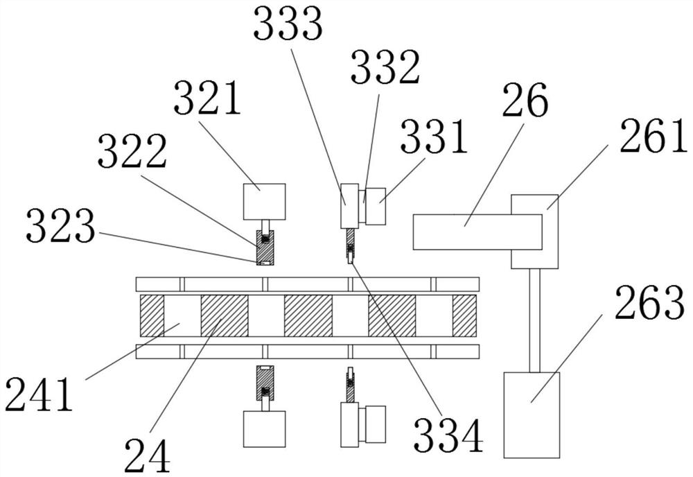
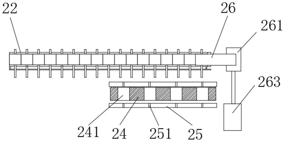
[0027] refer to figure 2 , the rotor moving mechanism 26 is vertically connected with a first cylinder 261 for vertical reciprocating motion, and the first cylinder 261 is horizontally connected with a second cylinder ...


PUM


Abstract

The invention provides a motor rotor shaft sleeve press-in machine which comprises a rack, a motor rotor positioning block is fixed to the rack, a shaft sleeve sleeve-in device and a shaft sleeve press-in device are symmetrically arranged on the two sides of the motor rotor positioning block, and a motor rotor pressing block is arranged above the motor rotor positioning block. The motor rotor pressing block is used for pressing a motor rotor positioned on the motor rotor positioning block, the shaft sleeve sleeve-in device is used for grabbing a shaft sleeve and preliminarily sleeving the shaft sleeve on a shaft of the motor rotor, and the shaft sleeve press-in device is used for pressing the preliminarily sleeved shaft sleeve into a specified position. The shaft sleeve press-in process is divided into two steps, namely a sleeve-in step and a press-in step, direct pressing of a shaft sleeve clamp on the shaft sleeve is replaced, the shaft sleeve is sleeved in place, two shafts of a motor rotor can be pressed at the same time, and the production efficiency is improved.

Description

technical field [0001] The invention relates to the technical field of motor rotors, in particular to a motor rotor shaft sleeve press-in machine. Background technique [0002] Referring to the Chinese patent CN201920615857.2, an automatic motor rotor bushing press-in device includes an operating table, a controller, a bushing vibration plate, a bushing guide rail, a bushing press-in assembly, a gasket press-in assembly, and a snap-in press-in Assembly and rotor guide rail, the sleeve guide rail is arranged in front of the shaft sleeve vibration plate, the other end of the sleeve guide rail is provided with a sleeve press-in assembly, the rotor guide rail is arranged in front of the shaft sleeve guide rail, the gasket The press-in assembly is arranged on one side of the rotor guide rail, two gasket press-in assemblies are arranged side by side, and the snap-in press-in assembly is arranged on the left side of the gasket press-in assembly; the sleeve press-in assembly include...

Claims


Application Information

Patent Timeline
Patent Type & Authority Applications(China)
IPC IPC(8): H02K15/02
CPCH02K15/02
Inventor 沈国平张媛蒋凯李磊谢盼盼
Owner HANGZHOU WEIGUANG ELECTRONICS
Why Eureka
Try Eureka