
Solid-state relay

A solid-state relay, bottom-fixed technology, applied in the direction of ventilation/cooling/heating of relays, can solve the problems of insufficient contact, low heat dissipation efficiency, insufficient heat area, etc., to facilitate addition and replacement, increase heat dissipation area, and speed up heat dissipation Effect

Active Publication Date: 2021-04-23
XIAMEN JINXINRONG ELECTRONICS
View PDF6 Cites 2 Cited by
  • Summary
  • Abstract
  • Description
  • Claims
  • Application Information

AI Technical Summary

Problems solved by technology

[0004] In the actual use of existing solid state relays, the contact between the heating surface and the heat dissipation structure is not sufficient, resulting in insufficient heat conduction area and low heat dissipation efficiency, and the heat dissipation area of ​​the solid state relay is small, and the air velocity on the surface of the heat dissipation structure is relatively low. Slow, the heat on the surface of the heat dissipation structure cannot be quickly dissipated into the air, resulting in low heat dissipation efficiency of the solid state relay, affecting the normal use of the solid state relay

Method used


Image

  • Solid-state relay
  • Solid-state relay
  • Solid-state relay

Examples


Embodiment Construction

[0028] In order to make the technical means, creative features, goals and effects achieved by the present invention easy to understand, the present invention will be further described below in conjunction with specific embodiments.

[0029] In describing the present invention, it is to be understood that the terms "center", "upper", "lower", "front", "rear", "left", "right", "vertical", "horizontal", The orientations or positional relationships indicated by "top", "bottom", "inner", "outer", etc. are based on the orientations or positional relationships shown in the drawings, and are only for the convenience of describing the present invention and simplifying the description, rather than indicating or implying the It should not be construed as limiting the invention that a device or element must have a particular orientation, be constructed, and operate in a particular orientation.

[0030] In the description of the present invention, it should be noted that, unless otherwise ...


PUM


Abstract

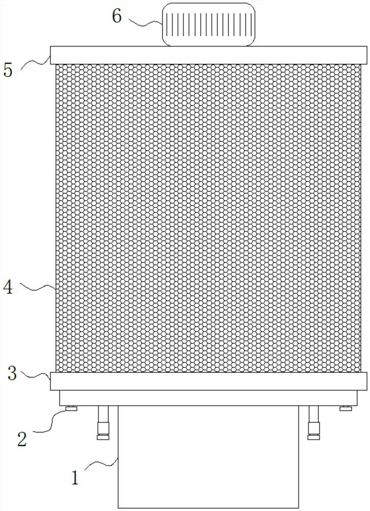
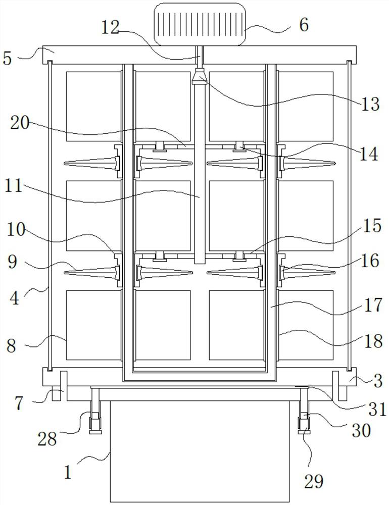
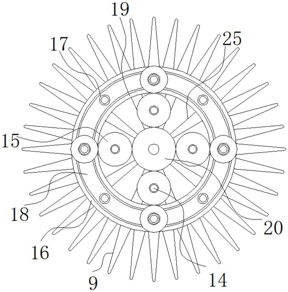
The invention belongs to the technical field of relay heat dissipation and discloses a solid-state relay. The solid-state relay comprises a heat conduction plate, a mounting plate, a heat conduction copper ring, a limiting ring A and a limiting ring B; a solid-state relay is fixedly installed at the bottom of the heat conduction plate; a heat conduction seam is formed in the middle of the top end of the solid-state relay; transparent pipes are symmetrically and fixedly installed on the left side and the right side of the bottom of the solid-state relay; inner cavities of the two transparent pipes are communicated with an inner cavity of the heat conduction seam; fixing screws are in threaded connection with the bottoms of the two transparent pipes; and rubber plugs are fixedly bonded to the tops of the two sets of fixing screws. In an actual use process, fan blades A and fan blades B blow air to heat dissipation fins A and heat dissipation fins B through rotation correspondingly, so that the air flow speed in the solid-state relay is increased, heat on the heat conduction copper pipe, the heat dissipation plate A, the heat dissipation plate B, the heat dissipation fins A and the heat dissipation fins B can be dissipated more quickly, and therefore, the heat dissipation speed of the solid-state relay is further increased.

Description

technical field [0001] The invention relates to the technical field of relay heat dissipation, in particular to a solid-state relay. Background technique [0002] Solid State Relay (SOLIDSTATERELAYS, hereinafter abbreviated as "SSR") is a new type of non-contact switching device composed of solid-state electronic components, which utilizes the switching characteristics of electronic components (such as switching transistors, triacs, etc. , It can achieve the purpose of connecting and disconnecting the circuit without contact and spark, so it is also called "contactless switch". [0003] The load of the solid-state relay is obviously related to the ambient temperature. As the temperature rises, the load capacity will drop rapidly. Therefore, it is necessary to dissipate the heat generated by the solid-state relay in time to avoid excessive temperature of the solid-state relay. [0004] In the actual use of existing solid state relays, the contact between the heating surface ...

Claims


Application Information

Patent Timeline
Patent Type & Authority Applications(China)
IPC IPC(8): H01H45/12
CPCH01H45/12
Inventor 饶明辉杨志威张怡培
Owner XIAMEN JINXINRONG ELECTRONICS
Learn More