
Annular detachable rubber probe sidewall contact device

A pusher and rubber technology, which is applied in measurement, wellbore/well parts, earthwork drilling and production, etc., can solve problems such as limited volume, unstable support foundation, insufficient friction, etc.

Active Publication Date: 2021-04-23
王少斌
View PDF19 Cites 0 Cited by
  • Summary
  • Abstract
  • Description
  • Claims
  • Application Information

AI Technical Summary

Problems solved by technology

[0004] However, since the parallel structure composed of the main arm, polar plate and auxiliary arm is deployed along the direction of gravity, the friction between it and the well wall is insufficient, which leads to unstable support foundation, and the polar plate is easily affected by the friction force of the downhole fluid. Swipe down to affect the measurement effect
[0005] In addition, since the angles of the main arm, pole plate, and auxiliary arm after opening are inclined parallelograms, the thrust applied to the main arm on the main base is not completely transmitted to the pole plate, but has a horizontal component force, and is affected by Limited to the volume of the main body, the thrust exerted by it also has an upper limit, which reduces the ultimate thrust of the polar plate, thereby affecting the support stability of the entire thruster

Method used


Image

  • Annular detachable rubber probe sidewall contact device
  • Annular detachable rubber probe sidewall contact device
  • Annular detachable rubber probe sidewall contact device

Examples


Embodiment Construction

[0023] The specific structure and implementation process of this solution will be described in detail below through specific embodiments and accompanying drawings.

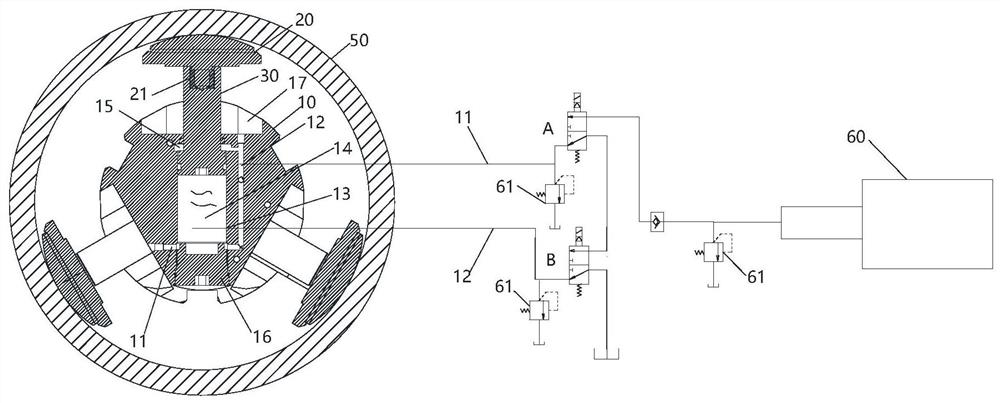
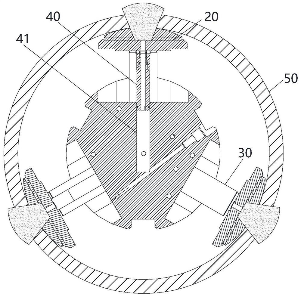
[0024] Such as figure 1 As shown, in one embodiment of the present invention, an annular detachable rubber probe pusher is disclosed, and the pusher can be connected with the main base, so that the pusher can realize supporting stay downhole. A specific pusher includes a body 10 , a pusher arm and a sampling tube 40 .

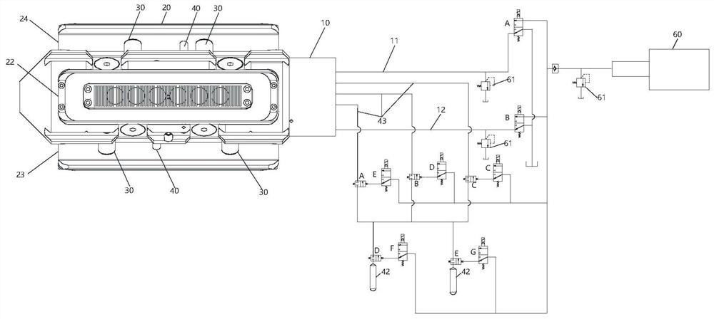
[0025] The machine body 10 is columnar, and it can be connected with the forward end of the main body through one end, so as to be an independent detachable part, such as figure 2 As shown, a high-pressure output oil circuit 11 and a high-pressure contraction oil circuit 12 are arranged inside the body 10, and the high-pressure output oil circuit 11 and the high-pressure contraction oil circuit 12 are respectively used to transport high-pressure hydraulic oil to drive the push arm to realize stre...


PUM


Abstract

The invention provides an annular detachable rubber probe sidewall contact device. The annular detachable rubber probe sidewall contact device comprises a cylindrical machine body, an eccentering arm and a sampling pipe, wherein a high-pressure output oil path and a high-pressure contraction oil path are arranged in the machine body, the eccentering arm comprises a plurality of polar plates which are symmetrically distributed on the outer circumference of the machine body, each polar plate is movably installed on the machine body through a piston rod perpendicular to the machine body, piston cavities for containing the piston rods are formed in the machine body, the piston cavities communicate with the high-pressure output oil path and the high-pressure contraction oil path, one end of the sampling pipe is connected with the polar plates, and the other end communicated with a sampling channel in the machine body through a sampling cavity in the machine body. According to the annular detachable rubber probe sidewall contact device, the high-pressure hydraulic oil directly pushes the piston rods to make contact with the well wall in the mode of being perpendicular to the well wall, the pressure of the high-pressure hydraulic oil in the high-pressure output oil path can be directly and evenly shared by all polar plates and then acts on the well wall, interference force cannot be generated, supporting thrust can be greatly improved, the sidewall contact device can stably stay at the supporting position, and a better sampling effect is achieved.

Description

technical field [0001] The invention relates to the field of downhole petroleum measurement, in particular to an annular detachable rubber probe pusher which vertically drives the push arm to contact the well wall to improve the supporting force. Background technique [0002] With the development of the petroleum industry, the exploration technology of petroleum exploration is constantly updated. The formation sampling instrument has always been an important part of the exploration equipment in the field of petroleum exploration. It is used to measure various data of the current drilling, such as inclination. The formation sampling instrument is generally installed on a pusher that can support and stay at a designated position in the downhole at any time. [0003] At present, the push arm of the pusher, regardless of the number of the push arm, mostly adopts the connecting rod structure composed of the main arm, the pole plate and the auxiliary arm. After the main arm, the p...

Claims


Application Information

Patent Timeline
Patent Type & Authority Applications(China)
IPC IPC(8): E21B47/00E21B49/00
CPCE21B47/00E21B49/00E21B49/10
Inventor 王少斌
Owner 王少斌
Learn More