Eureka AIR delivers breakthrough ideas for toughest innovation challenges, trusted by R&D personnel around the world.

Touch screen laminating equipment

A technology of laminating equipment and touch screen, applied in the directions of external support, transportation and packaging, winding strips, etc., can solve the problems of unstable attachment effect, offset size of lamination, low work efficiency, etc., and achieve good filming effect, Guarantee the film position and increase the effect of production efficiency

Active Publication Date: 2021-04-23
深圳市汇凌信息技术有限公司
View PDF0 Cites 3 Cited by
  • Summary
  • Abstract
  • Description
  • Claims
  • Application Information

AI Technical Summary

Problems solved by technology

[0002] At present, most smart electronic devices on the market have adopted touch display modules, and touch screens are widely used as one of the key components of touch display modules, and touch screens are assembled in the later stage to prevent surface wear and dust Need, after the production is completed, the touch screen needs to be pasted with a film on its surface to protect the touch screen from abrasion during the assembly process. In the prior art, a single film is usually manually attached to a single touch screen one by one, but through Manual attachment is obviously inefficient, and after the attachment is completed, it is easy to have a deviation in the size of the attachment, which will eventually lead to unstable attachment effects and lead to defective products.

Method used


Image

  • Touch screen laminating equipment
  • Touch screen laminating equipment
  • Touch screen laminating equipment

Examples


Embodiment 1

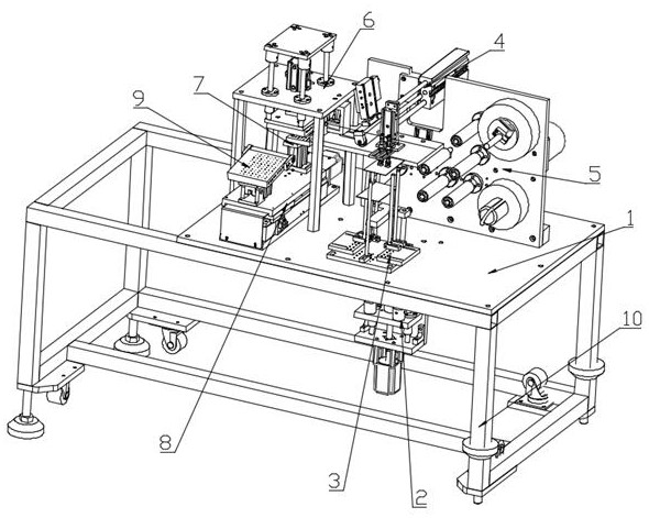
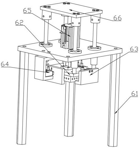
[0031] Such as figure 1 As shown, Embodiment 1 of the present invention: a touch screen bonding equipment, including a frame 10, a bottom plate 1, a feeding mechanism 2, a feeding auxiliary assembly 3, a retrieving mechanism 4, a film conveying mechanism 5, and a correction and pressing mechanism 6 , a hot compress mechanism 7, a longitudinal conveying mechanism 8 and a smoothing mechanism 9, the bottom plate 1 is arranged on the upper part of the frame 10, the film coating conveying mechanism 5 is arranged transversely on the right end rear side of the bottom plate 1, the The feeding mechanism 4 is longitudinally arranged on the top of the film conveying mechanism 5, the feeding auxiliary assembly 3 is arranged on the right front side of the bottom plate 1, and the feeding mechanism 2 is arranged on the right front back of the bottom plate 1 , and pass through the bottom plate 1 upwards and are located at the lower part of the auxiliary feeding assembly 3, the longitudinal co...


PUM


Abstract

The invention discloses touch screen laminating equipment which comprises a rack, a bottom plate, a feeding mechanism, a feeding assisting assembly, a material taking mechanism, a film laminating and conveying mechanism, a correcting and pressing mechanism, a hot compress mechanism, a longitudinal conveying mechanism and a trowelling mechanism. The bottom plate is arranged on the upper part of the rack; the film laminating and conveying mechanism is transversely arranged on the rear side of the right end of the bottom plate; the feeding mechanism is arranged on the back of the front side of the right end of the bottom plate; the longitudinal conveying mechanism is longitudinally arranged at the left end of the bottom plate; the hot compress mechanism is arranged on the left side of the upper part of the longitudinal conveying mechanism; the trowelling mechanism is arranged on the right side of the upper part of the longitudinal conveying mechanism; and the correcting and pressing mechanism is arranged at the right end of the bottom plate. According to the touch screen laminating equipment provided by the invention, the film pasting efficiency can be improved,the film pasting position is guaranteed, film pasting position deviation is effectively avoided, the film pasting effect is good, the reject ratio is greatly reduced, consumables are saved, the production benefits are increased, and the touch screen laminating equipment has a good market application value.

Description

technical field [0001] The invention relates to the technical field of touch screen assembly equipment, in particular to a touch screen bonding equipment. Background technique [0002] At present, most smart electronic devices on the market have adopted touch display modules, and touch screens are widely used as one of the key components of touch display modules, and touch screens are assembled in the later stage to prevent surface wear and dust Need, after the production is completed, the touch screen needs to be pasted with a film on its surface to protect the touch screen from abrasion during the assembly process. In the prior art, a single film is usually manually attached to a single touch screen one by one, but through Manual attachment is obviously inefficient, and after the attachment is completed, it is easy to cause a deviation in the size of the attachment, which eventually leads to unstable attachment effects and the production of defective products. [0003] Th...

Claims


Application Information

Patent Timeline
IPC IPC(8): B65B33/02B65B61/24B65B41/06B65B41/14B65H16/00B65H16/04B65H18/08B65H18/02
CPCB65B33/02B65B61/24B65B41/06B65B41/14B65H16/00B65H16/04B65H18/08B65H18/026B65H2701/1944
Inventor 崔小燕顾成文
Owner 深圳市汇凌信息技术有限公司
Why Eureka
Eureka Blog
Learn More