Glass mold clamp for cutting off casting head

A technology of glass molds and pouring risers, which is applied in the field of tooling and fixtures, to reduce the intensity of clamping operations, ensure reliability, and increase the effect of clamping speed

Active Publication Date: 2021-04-23
CHANGSHU JIANHUA MOLD TECH
View PDF29 Cites 0 Cited by
  • Summary
  • Abstract
  • Description
  • Claims
  • Application Information

AI Technical Summary

Problems solved by technology

It is based on the aforementioned factors that none of the Chinese and foreign patent documents published so far has been found to be suitable for the clamping of glass molds with sprue risers for casting and to meet the requirement of no interference to the removal of sprue risers in the clamped state. The technical information of the fixture, the technical solution to be introduced below is generated under this background

Method used


Image

  • Glass mold clamp for cutting off casting head
  • Glass mold clamp for cutting off casting head

Examples


Embodiment Construction

[0015] In order to understand the technical essence and beneficial effects of the present invention more clearly, the applicant will describe in detail the following examples, but the descriptions of the examples are not intended to limit the solutions of the present invention. Equivalent transformations that are only formal but not substantive should be regarded as the scope of the technical solution of the present invention.

[0016] In the following descriptions, all concepts involving directionality or orientation of up, down, left, right, front and rear are aimed at figure 1 As far as the position and state of the present invention are concerned, it cannot be understood as a special limitation on the technical solution provided by the present invention.

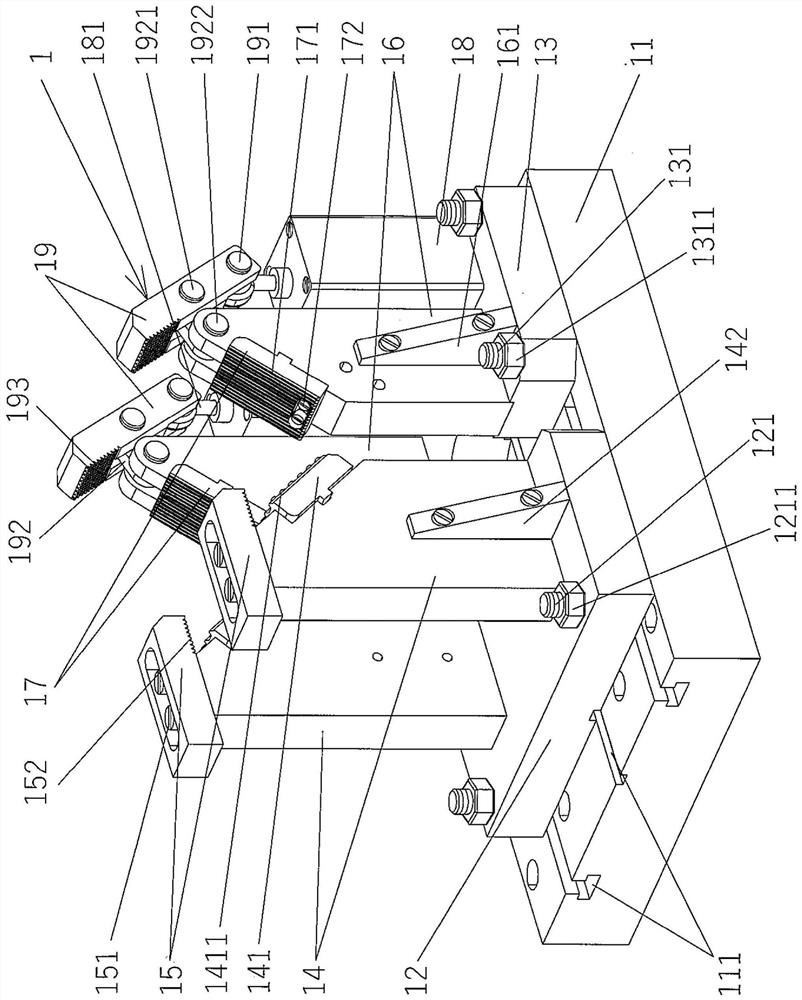
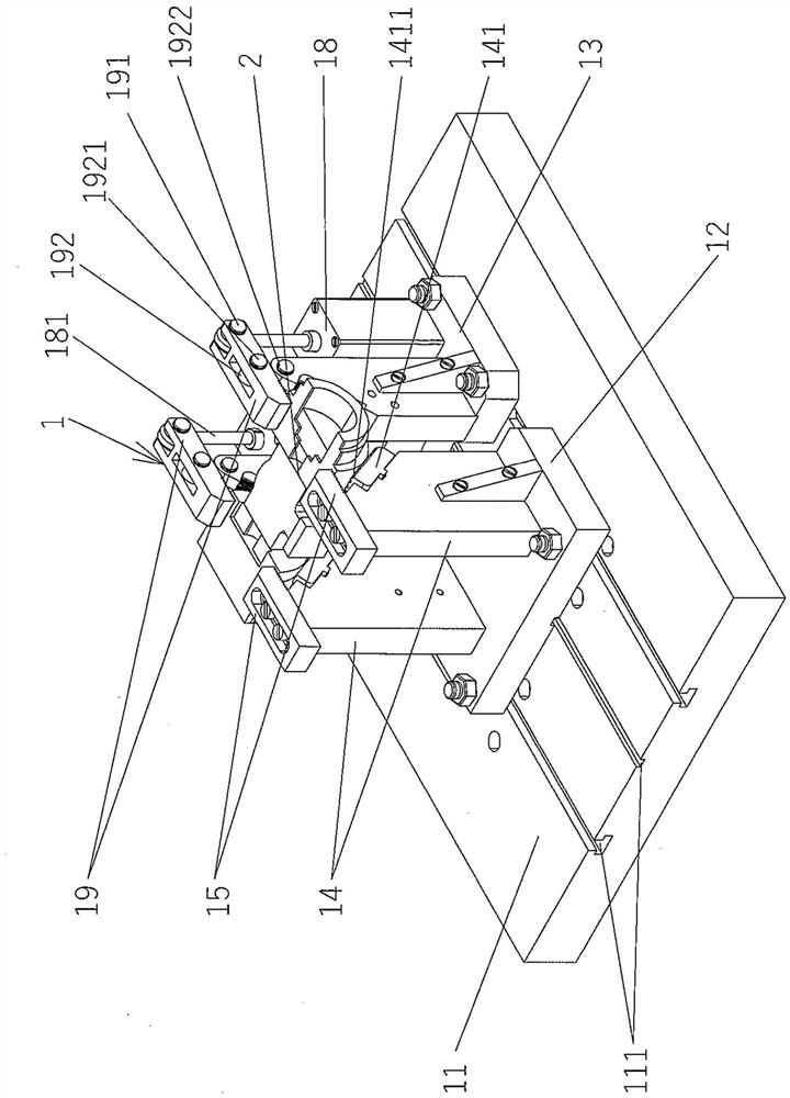
[0017] See figure 1, shows a clamp assembly 1, which comprises a clamping platform 11, a left adjustment plate 12, a right adjustment plate 13, a pair of fixed presser foot support plates 14, a pair of fixed presser fee...


PUM


Abstract

A glass mold clamp for cutting off a casting head comprises a clamp assembly, wherein the assembly comprises a clamping platform, a left adjusting plate, a right adjusting plate, a pair of fixed presser foot supporting plates, a pair of fixed presser feet, a pair of mold supporting palm supporting plates, a pair of mold supporting palms, a pair of movable presser foot driving acting cylinders and a pair of movable presser feet, a bolt matching groove is formed in the clamping platform, the left adjusting plate is fixed to the upward side of the left end of the clamping platform, the right adjusting plate is fixed to the upward side of the right end of the clamping platform, the pair of fixed presser foot supporting plates are formed on the left adjusting plate, the pair of fixed presser feet are fixed to the tops of the pair of fixed presser foot supporting plates, and the pair of mold supporting palm supporting plates are formed on the rear adjusting plate. The pair of die supporting palms and the pair of die supporting palm supporting plates are fixed, the pair of movable presser foot driving acting cylinders are fixed to the rear adjusting plate, the right ends of the pair of movable presser feet are hinged to the tail ends of the movable presser foot driving acting cylinder columns, hinge bases are arranged in the middles, and the left ends form free ends. The clamping speed is increased, and the operation intensity is reduced; and it is reliable to clamp.

Description

technical field [0001] The invention belongs to the technical field of tooling fixtures, and in particular relates to a glass mold fixture for cutting off a pouring riser. Background technique [0002] The aforementioned glass molds mainly refer to cast copper alloy dies, but are not absolutely limited to cast copper alloy dies. The function of a sprue riser is well known in the foundry industry, specifically, it is a supplementary part added to the top and / or sides of a casting in order to avoid defects in the casting. In the casting mold, the cavity of the sprue riser is a container for storing liquid metal, and its function is various. The form, size and opening position of the sprue riser with different functions are not the same. In view of this, the sprue riser The design needs to take into account the characteristics of castings of different products. In the patent documents that are not limited to the following examples, technical information related to glass mold ...

Claims


Application Information

Patent Timeline
Patent Type & Authority Applications(China)
IPC IPC(8): B23Q3/08
Inventor 苏秋君郁伟峰韩志强沈军曹明芳李旦
Owner CHANGSHU JIANHUA MOLD TECH
Why Eureka
Try Eureka