
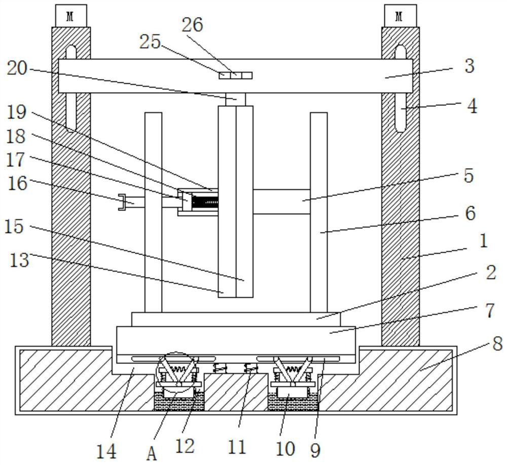
An optical cable torsion test device

A torsion test and optical cable technology, applied in the field of optical fiber, can solve the problems of many transmission links, affecting the test effect, and complex structure.

Inactive Publication Date: 2020-10-30
安徽电信器材贸易工业有限责任公司
View PDF8 Cites 0 Cited by
  • Summary
  • Abstract
  • Description
  • Claims
  • Application Information

AI Technical Summary

Problems solved by technology

[0003] The purpose of the present invention is to solve the shortcomings of the prior art, such as: 1. Too many transmission links increase the energy consumption of the structure; 2. Most of them use rack and pinion to cooperate, and the complex structure affects the test effect at the same time; 3. 1. The installation and disassembly are inconvenient, which increases the work intensity of the installation; 4. The lack of shock absorbing device causes the equipment to be damaged too quickly

Method used


Image

  • An optical cable torsion test device
  • An optical cable torsion test device
  • An optical cable torsion test device

Examples


Embodiment Construction

[0019] The following will clearly and completely describe the technical solutions in the embodiments of the present invention with reference to the accompanying drawings in the embodiments of the present invention. Obviously, the described embodiments are only some, not all, embodiments of the present invention.

[0020] In describing the present invention, it should be understood that the terms "upper", "lower", "front", "rear", "left", "right", "top", "bottom", "inner", " The orientation or positional relationship indicated by "outside", etc. is based on the orientation or positional relationship shown in the drawings, and is only for the convenience of describing the present invention and simplifying the description, rather than indicating or implying that the referred device or element must have a specific orientation, so as to Specific orientation configurations and operations, therefore, are not to be construed as limitations on the invention.

[0021] refer to Figure ...


PUM


Abstract

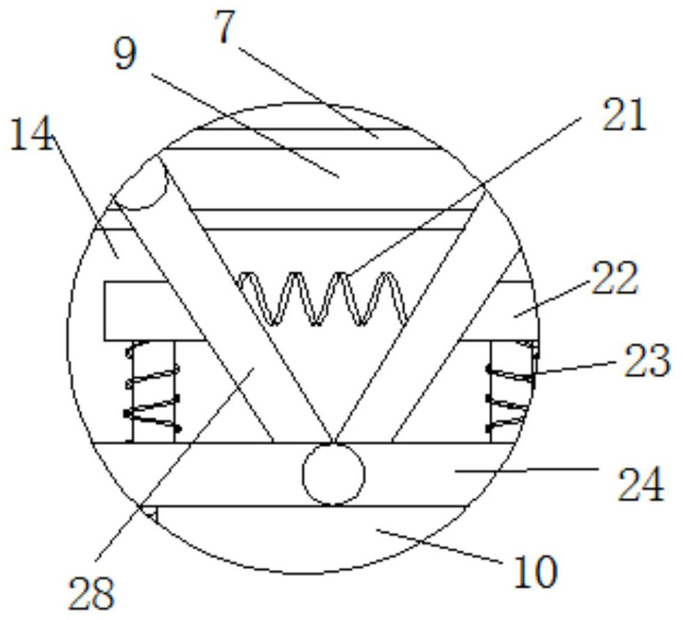
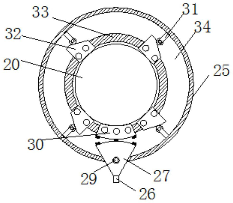
The invention discloses an optical cable torsion testing apparatus. The optical cable torsion testing apparatus comprises a pedestal, a second installation groove is arranged at the pedestal, a firstinstalling plate is arranged at the second installation groove, a damping device is arranged at one side of the first installing plate, a torsion apparatus is arranged at the opposite side of the first installing plate, two columns are symmetrically arranged at the pedestal, a second chute is arranged on each column, a telescoping apparatus is arranged in the second chute, and the chute is connected with a movable plate through the telescoping apparatus. The optical cable torsion testing apparatus has the advantages of simple structure and easy operation, 1) a motion transmission link is obviously reduced, and energy consumption of a power mechanism is saved; 2) cooperation of wheel and rack is not used for the apparatus, the structure is obviously simplified, and the testing effect on anoptical cable is guaranteed; 3) clamping on the optical cable is fast and reliable, and clamping work intensity on the optical cable is mitigated; and 4) parts can be better protected through the damping device, and over-fast damaging can be avoided.

Description

technical field [0001] The invention relates to the field of optical fiber technology, in particular to an optical cable torsion test device. Background technique [0002] The torsion test of the optical cable is an indispensable link for the quality supervision and inspection agencies of optical cable products and even the optical cable manufacturers to grasp the quality of the optical cable. The equipment that the optical cable torsion test relies on is the aforementioned optical cable torsion test device. Torsion test, and after the end of the test, the optical cable is used for subsequent instrument measurement such as loss, reflection, light transmission performance, etc., so as to grasp the quality of the optical cable, the existing optical cable torsion test device has the following shortcomings; 1. There are too many transmission links, Increased energy consumption of the structure; 2. Most of them use rack and pinion to cooperate, and the complex structure affects t...

Claims


Application Information

Patent Timeline
Patent Type & Authority Patents(China)
IPC IPC(8): G01N3/22
CPCG01N3/22G01N2203/0021G01N2203/005G01N2203/028
Inventor 陈铁牛张坤黄晓玲
Owner 安徽电信器材贸易工业有限责任公司
Learn More