A sheet metal cutting box
A sheet metal, box body technology, applied in metal processing equipment, metal processing machinery parts, maintenance and safety accessories, etc., can solve the problems of difficult collection of debris, waste of metal resources, generation of metal debris, etc. , The effect of preventing noise transmission and not easy to shake
- Summary
- Abstract
- Description
- Claims
- Application Information
AI Technical Summary
Problems solved by technology
Method used
Image


Examples
Embodiment 1
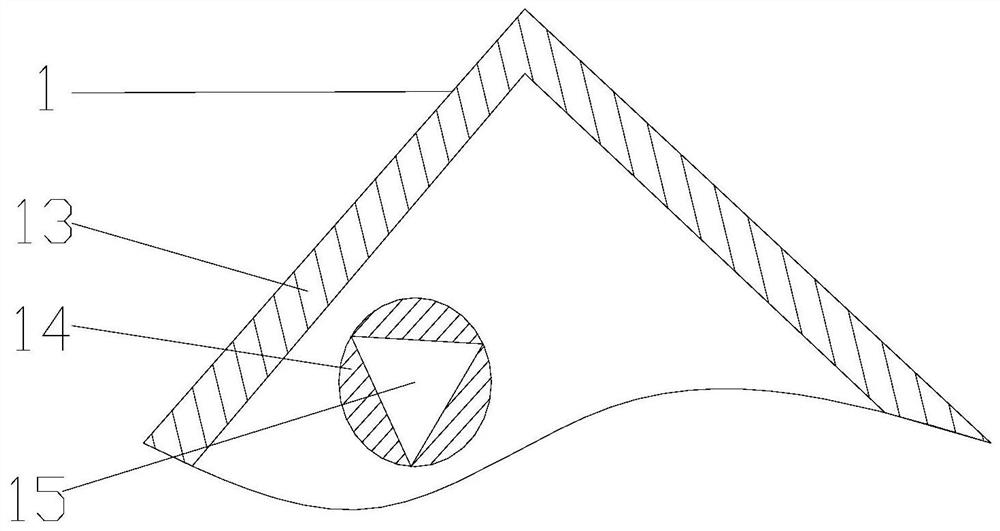
[0034] Such as Figure 1-2 , the present invention provides a technical solution: a thin-plate metal cutting box, including a box body 1, a controller 2 is fixedly connected to the middle position of the front top of the box body 1, and a display screen 12 is arranged in the middle of the front top top of the controller 2 to display The front bottom of the screen 12 is provided with a control key 11, the left middle part of the box body 1 is provided with a discharge port 5, the right side middle part of the box body 1 is provided with a material inlet 8, and both sides of the bottom of the box body 1 are fixedly connected with The wheels 7 are fixedly connected with support frames 3 on both sides of the inner cavity top of the box body 1, and the middle position of the inner cavity top of the box body 1 is provided with an electric box 4, and the bottom of the electric box 4 is fixedly connected with a protective cover 10, and the protective cover 10 The bottom is provided wi...
Embodiment 2
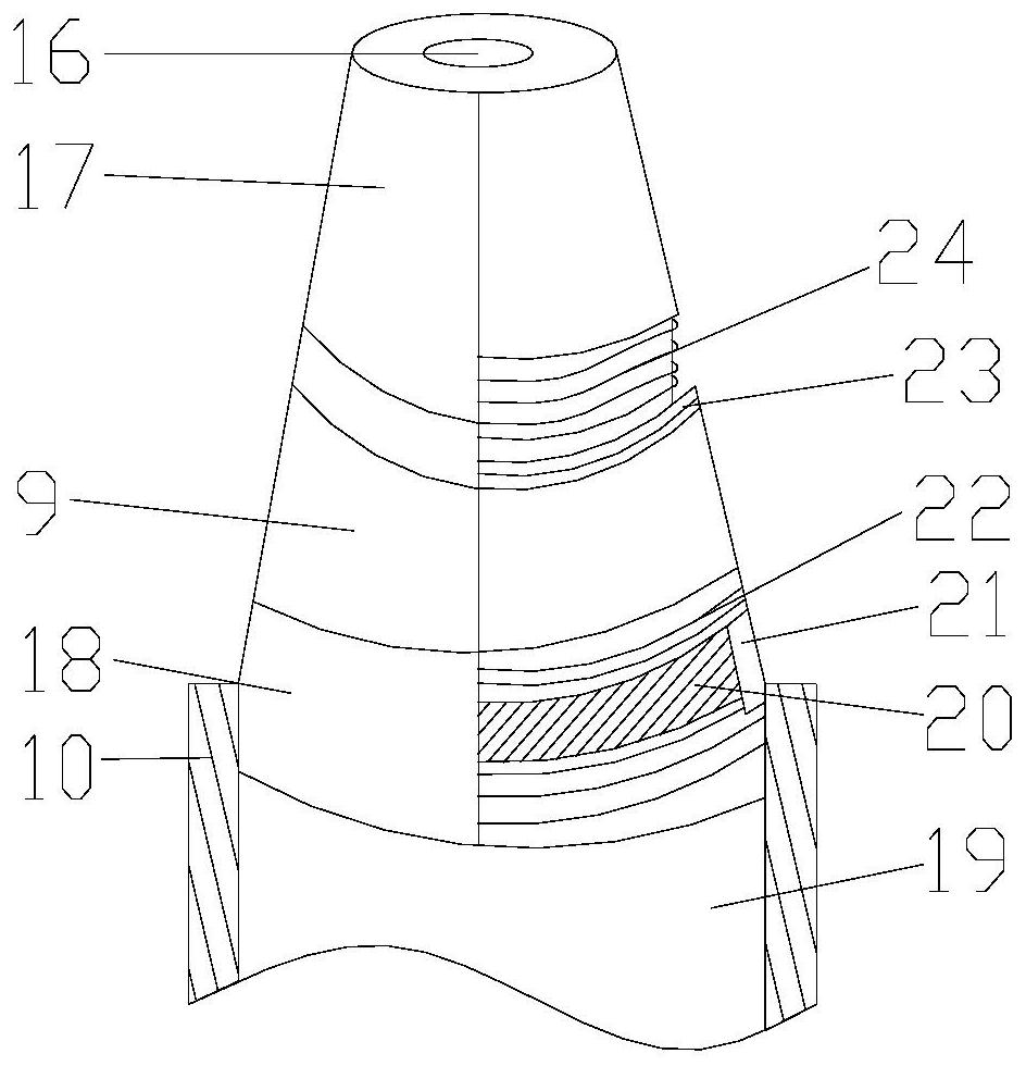
[0038] Such as Figure 1-4 As shown, on the basis of Embodiment 1, the present invention provides a technical solution: the inside of the protective cover 10 is provided with a connecting piece 19, the bottom inner wall of the connecting piece 19 is provided with a groove 21, and the bottom outer surface of the connecting piece 19 is provided with There is a fixing device 18, the bottom inner wall of the fixing device 18 is threadedly connected with the work piece 9, the top of the work piece 9 is fixedly connected with a bump 20, and the top outer surface of the work piece 9 is provided with a second screw thread 22 inside the fixing device 18, The bottom inner wall of work piece 9 is provided with screw groove 23, and the bottom of work piece 9 is threadedly connected with cutting base 17, and the top of cut base 17 is fixedly connected with threaded rod 24, and the bottom middle position of cutting base 17 is provided with cutting head 16.
[0039]Wherein, the fixing device...
Embodiment 3
[0042] Such as Figure 1-6 As shown, on the basis of Embodiment 1 and Embodiment 2, the present invention provides a technical solution: a fixed block 29 is provided at the inner middle position of the work piece 9, and a communication hole 30 is opened at the bottom middle position of the fixed block 29 to fix the The outer surface of block 29 is fixedly connected with connecting rod 31, and the end of connecting rod 31 away from fixed block 29 is fixedly connected with connecting layer 27, and the bottom of connecting layer 27 is provided with communicating port 28, and connecting layer 27 is fixed away from the side of connecting rod 31. A sealing ring 26 is connected, and a cooling hole 25 is opened between the sealing ring 26 and the work piece 9 .
[0043] Wherein, the side of the connection layer 27 close to the seal ring 26 is provided with a guide port 32 , and the side of the connection layer 27 close to the communication port 28 is fixedly connected with a connectio...
PUM
 Abstract
Description
Claims
Application Information
 - R&D
- Intellectual Property
- Life Sciences
- Materials
- Tech Scout
- Unparalleled Data Quality
- Higher Quality Content
- 60% Fewer Hallucinations
Browse by: Latest US Patents, China's latest patents, Technical Efficacy Thesaurus, Application Domain, Technology Topic, Popular Technical Reports.
© 2025 PatSnap. All rights reserved.Legal|Privacy policy|Modern Slavery Act Transparency Statement|Sitemap|About US| Contact US: help@patsnap.com