Nuclear power station plant water pump shaft seal water supply system

A supply system, water pump shaft technology, applied in the water supply pipeline system, nuclear power generation, pumping station, etc., can solve the problems that affect the life of the shaft seal, shaft seal wear, etc., achieve fast response, eliminate human errors, and ensure independence Effect

Active Publication Date: 2021-04-20
SANMEN NUCLEAR POWER CO LTD
View PDF14 Cites 0 Cited by
  • Summary
  • Abstract
  • Description
  • Claims
  • Application Information

AI Technical Summary

Problems solved by technology

Although the plant water pump in this scheme does not require external supply of shaft seal water, the pump has high independence in operation, but in the start-up phase of the pump, the pump cannot provide shaft seal water for itself. At this time, the pump must be started with dry friction. In addition, during normal operation The shaft seal water provided by the pump is seawater containing sediment and salt, which will cause serious wear and tear on the shaft seal, thus affecting the life of the shaft seal

Method used


Image

  • Nuclear power station plant water pump shaft seal water supply system
  • Nuclear power station plant water pump shaft seal water supply system

Examples


Embodiment 1

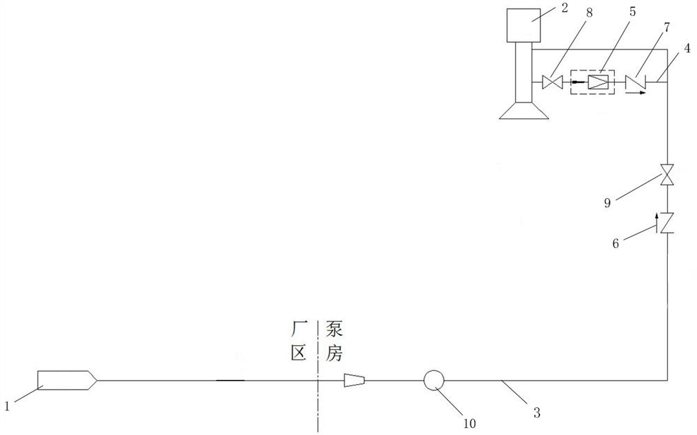
[0028] like figure 1 As shown, a nuclear power plant plant water pump shaft seal water supply system includes a production water distribution system 1, a water supply pipeline 3 connecting the production water distribution system 1 and the plant water pump 2, and is located at the water outlet of the plant water pump 2 and the The emergency water supply pipeline 4 between the water supply pipelines 3, the pressure reducing valve 5 arranged on the emergency water supply pipeline 4, the valve located upstream of the emergency water supply pipeline 4 on the described water supply pipeline 3 The first check valve 6, the water pressure in the emergency water supply pipeline 4 at the end of the pressure reducing valve 5 close to the water supply pipeline 3 is lower than the water pressure in the water supply pipeline 3, and the water supply pipeline The water pressure in 3 is lower than the water pressure at the water outlet of the plant water pump 2. Of course, the decompression v...

Embodiment 2

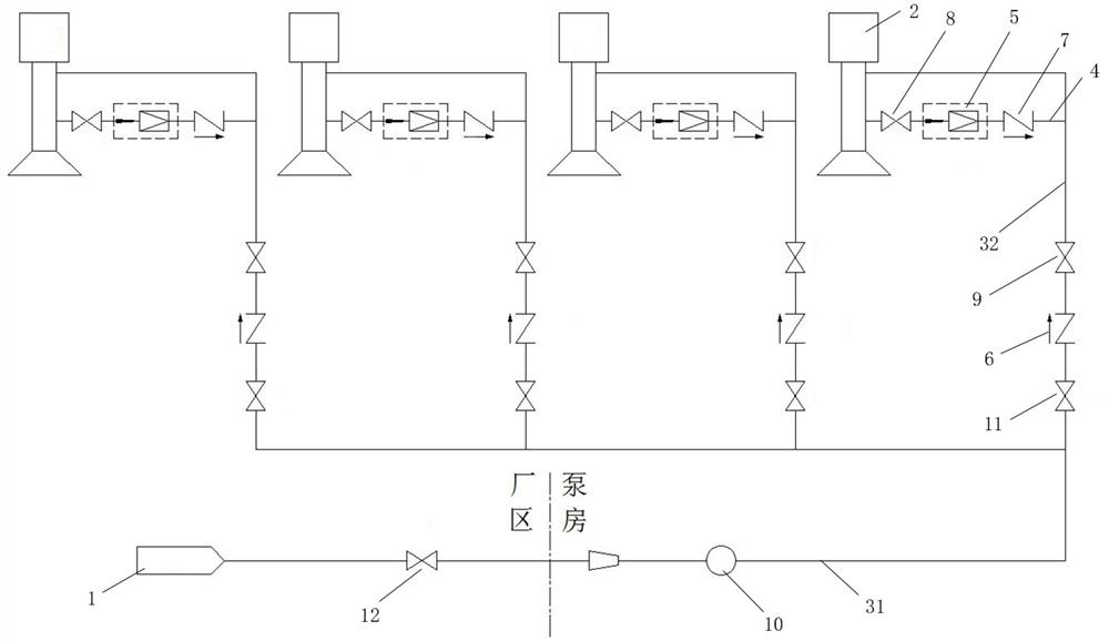
[0033] like figure 2As shown, different from Embodiment 1, the plant water pump 2 has multiple, and the water supply pipeline 3 includes a main pipe 31 connected to the production water distribution system 1, and a pipe connected to each plant water pump 2 respectively. A branch pipe 32 , the emergency water supply pipeline 4 is connected to the branch pipe 32 , and the first check valve 6 is arranged on the branch pipe 32 . The end of the branch pipe 32 connected to the main pipe 31 is provided with a third isolation valve 11, which is mainly used to control the opening and closing of the water supply of different branch pipes, so as to improve the controllability and facilitate the detection of the water supply conditions of different branch pipes. The main pipe 31 is provided with a fourth isolation valve 12 for controlling the water supply of the main pipe. The main pipe 31 is provided with a flow meter 10, and when testing the water supply of a single branch pipe, it is...


PUM


Abstract

The invention provides a nuclear power station plant water pump shaft seal water supply system, and belongs to the technical field of water pump shaft seal water supply. The nuclear power station plant water pump shaft seal water supply system comprises a production water distribution system, a water supply pipeline connected with the production water distribution system and a plant water pump, an emergency water supply pipeline arranged between a water outlet of the plant water pump and the water supply pipeline, a pressure reducing device arranged on the emergency water supply pipeline, and a first check valve arranged on the water supply pipeline and located on the upstream portion of the position connected with the emergency water supply pipeline, wherein the water pressure of the end, close to the water supply pipeline, of the pressure reducing device in the emergency water supply pipeline is lower than the water pressure in the water supply pipeline, and the water pressure in the water supply pipeline is lower than the water pressure of the water outlet of the plant water pump. According to the nuclear power station plant water pump shaft seal water supply system, the shaft seal water source can be automatically switched, independence and reliability of shaft seal water are guaranteed, the service life of a shaft seal is prolonged, and therefore the unit running safety and economical efficiency are improved.

Description

technical field [0001] The invention relates to the technical field of pump shaft seal water supply, in particular to a pump shaft seal water supply system for nuclear power plants. Background technique [0002] The fluid sucked by the plant water pump of nuclear power plant is seawater containing sediment and salt. At present, the plant water pump is mature and the common shaft seal water supply system has two forms. One form is to provide the shaft seal water of the pump by several clean fresh water pipelines. It is called scheme A; the other starts from the independence of pump operation, and the shaft seal water is provided by the pump itself, which is called scheme B. [0003] In scheme A, under normal conditions, the shaft seal water is provided by the drinking water system and raw water system from the water plant, and the two water sources share the common water supply main pipe. In the event of damage to the common water supply main, shaft seal water is provided by...

Claims


Application Information

Patent Timeline
IPC IPC(8): E03B1/02E03B5/02E03B7/02E03B7/07
CPCY02E30/30
Inventor 张一帆唐钢陈军张培来蔡龙霆施奇平汪方文王鹏程
Owner SANMEN NUCLEAR POWER CO LTD
Why Eureka
Try Eureka