
Photonic crystal coating equipment for surface of ultrathin flexible base material

A technology of flexible substrates and photonic crystals, which is applied in the direction of winding strips, thin material processing, metal material coating technology, etc., can solve the problem that the edge cannot be coated, the edge of the flexible material is easy to warp, and the flexible material is inconvenient to collect, etc. question

Pending Publication Date: 2021-04-20
YANCHENG INST OF TECH
View PDF12 Cites 0 Cited by
  • Summary
  • Abstract
  • Description
  • Claims
  • Application Information

AI Technical Summary

Problems solved by technology

However, there are some problems in the current coating equipment: 1. When coating flexible materials, the edge of the flexible material is easy to lift, resulting in the inability to coat the edge; 2. The flexible material is not easy to collect after coating

Method used


Image

  • Photonic crystal coating equipment for surface of ultrathin flexible base material
  • Photonic crystal coating equipment for surface of ultrathin flexible base material
  • Photonic crystal coating equipment for surface of ultrathin flexible base material

Examples


Embodiment

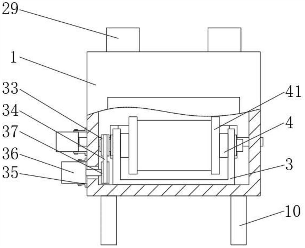
[0028] A photonic crystal coating device on the surface of an ultra-thin flexible substrate, including a box body 1, a partition plate 2, a bracket 3, a connecting block 4, a drive shaft 5, a roller 6, a conveyor belt 7, a motor frame 1 8, a servo motor 9, and support legs 10 and a coating machine 11, the inside of the box 1 is fixedly connected with a partition 2, the inside of the box 1 is fixedly connected with a bracket 3, and the inside of the bracket 3 is rotatably connected with two symmetrically distributed connecting blocks 4 , the inside of the box 1 is rotationally connected with two symmetrically distributed drive shafts 5, the outer side of the drive shaft 5 is fixedly connected with a roller 6, and the outer side of the roller 6 is sleeved with a conveyor belt 7, and the box 1 Two symmetrically distributed motor frames one 8 are fixedly connected to the outer side of the motor frame one 8, and a servo motor 9 is connected to the inner sides of the two motor frames...


PUM


Abstract

The invention discloses photonic crystal coating equipment for the surface of an ultrathin flexible base material. The photonic crystal coating equipment comprises a box body, a partition plate, a support, connecting blocks, driving shafts, rollers, a conveying belt, first motor frames, a servo motor, supporting legs and a coating machine, wherein the partition plate is fixedly connected into the box body, and the support is fixedly connected into the box body; the two symmetrically-distributed connecting blocks are rotatably connected to the interior of the support, the two symmetrically-distributed driving shafts are rotatably connected to the interior of the box body, the rollers are fixedly connected to the outer sides of the driving shafts, the outer sides of the rollers are sleeved with the conveying belt, and the two symmetrically-distributed first motor frames are fixedly connected to the outer side of the box body; and the inner sides of the two first motor frames are jointly connected with the servo motor. The invention relates to the photonic crystal coating equipment for the surface of the ultrathin flexible base material. The photonic crystal coating equipment has the characteristics of being capable of preventing edge curling and facilitating material collection.

Description

technical field [0001] The invention belongs to the technical field of photonic crystal coating, in particular to a photonic crystal coating equipment on the surface of an ultra-thin flexible substrate. Background technique [0002] A photonic crystal refers to an artificial periodic dielectric structure with a photonic band gap (Photonic Band-Gap, PBG for short), and is sometimes called a PBG photonic crystal structure. The so-called photonic bandgap means that waves in a certain frequency range cannot propagate in this periodic structure, that is, there is a "forbidden band" in this structure itself. [0003] This concept was originally proposed in the field of optics, and its research scope has been extended to microwave and acoustic wave bands. Since the periodic size of this structure is comparable to the wavelength corresponding to the central frequency of the "forbidden band", this structure is easier to realize in the microwave band than in the optical wave band. H...

Claims


Application Information

Patent Timeline
IPC IPC(8): B65H20/10B65H23/34B65H23/26B65H18/10B65H18/02C23C26/00
Inventor 孟灵灵黄新民敖翔汪诚威
Owner YANCHENG INST OF TECH
Learn More