
Installing and positioning method for parts on outer surfaces of blades of wind turbine generator

A technology for installation and positioning of wind turbines, which is applied to wind power generation, wind engines, engines, etc., can solve the problems of location accuracy and poor quality that consume a long time, save operating hours, determine the location accurately and reliably, and facilitate search Effect

Pending Publication Date: 2021-04-20
GUANGDONG MINGYANG WIND POWER IND GRP CO LTD
View PDF4 Cites 1 Cited by
  • Summary
  • Abstract
  • Description
  • Claims
  • Application Information

AI Technical Summary

Problems solved by technology

[0004] For the parts that need to be positioned as mentioned above, the commonly used method is to pull a steel ruler on the ground after the blade is demoulded, laser or measure directly along the blade surface from the blade root or blade tip, which not only takes a long time but also The location found is not accurate enough

Method used


Image

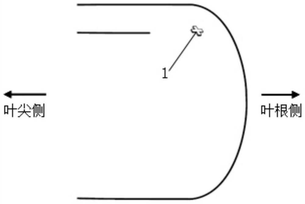
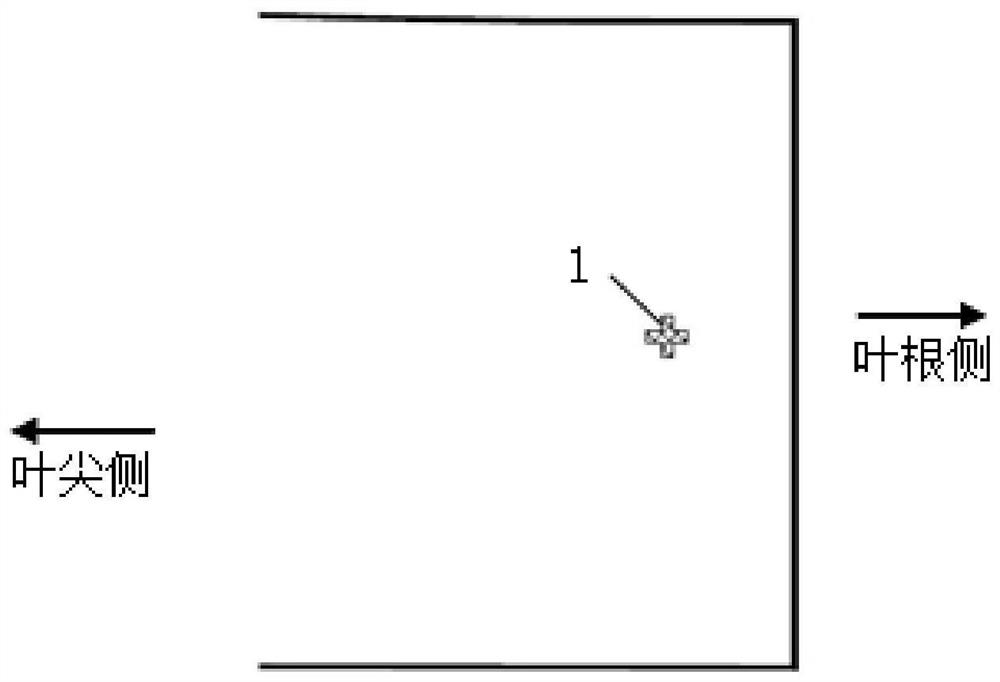
  • Installing and positioning method for parts on outer surfaces of blades of wind turbine generator
  • Installing and positioning method for parts on outer surfaces of blades of wind turbine generator
  • Installing and positioning method for parts on outer surfaces of blades of wind turbine generator

Examples


Embodiment Construction

[0029] The present invention will be further described below in conjunction with specific examples.

[0030] This embodiment provides a method for installing and positioning components on the outer surface of a blade of a wind turbine, comprising the following steps:

[0031] 1) Positioning in the mold

[0032] First, according to the chord and axial data of the component installation position (such as lightning receptors, vortex generators, noise reduction sawtooth blades, etc.) or operating positions (such as counterweight position, weighing position, etc.) Accurately measure the corresponding data on the inner surface of the mold and draw marks; the female mold is the basis for making blades, and its accuracy directly determines the accuracy of the blade shape. It is easy to find, it is a very direct, relatively accurate and easy-to-operate way to mark on the inner surface of the female mold through its meter mark and the leading and trailing edges, and then transfer to th...


PUM


Abstract

The invention discloses an installing and positioning method for parts on outer surfaces of blades of wind turbine generator. The method comprises the following steps that corresponding data on the inner surface of a blade production female mold are measured according to chordwise and axial data of part installing positions or part operation positions, and marks are drawn; the drawn marks are converted into permanent marks, and the inner surfaces of the marks need to be processed to be smooth; when the number of the positions needing to be marked is large and the distance between the positions is short, character labels are pasted near the positions, the labels are pasted to the surface of the female mold, and the surfaces of the labels need to be covered with small demolding cloth or easy-to-tear films; for the positioning position of a lightning arrester, a mark is drawn on the upper surface of the cloth layer according to the marks on the inner surface of the female mold after the laying is finished; and the outer surface of the blade separated from the female mold can present protruding marks corresponding to the marks on the female mold, the protruding marks can be used as the direct basis for subsequent root cutting, lightning arrester installation, weighing and balance weight positioning, and the protruding marks only need to be polished to be flat and coated with paint before the blade leaves a factory. By means of the method, part installation and necessary production operation can be conducted rapidly, easily, conveniently and accurately.

Description

technical field [0001] The invention relates to the technical field of wind turbine blades, in particular to a method for installing and positioning components on the outer surface of a wind turbine blade. Background technique [0002] As a clean and environmentally friendly renewable energy, wind energy has attracted widespread attention. Wind turbines are important equipment for realizing wind energy conversion, and wind turbine blades are one of the key components of wind turbines. [0003] The current mainstream manufacturing method of wind turbine blades is to lay fiber cloth, core materials and vacuum auxiliary materials in the shell mold, and then solidify them by vacuum infusion. After that, the two half shells are cemented, pressurized, cured and then demolded. For the rear section of the perforated blade, the root end is first cut along the zero position, and finally it also involves the positioning and installation of key small components such as the lightning rec...

Claims


Application Information

Patent Timeline
IPC IPC(8): B29C70/30B29C70/54F03D80/00F03D80/30B29L31/08
CPCY02E10/72Y02P70/50
Inventor 姬凌云房永增高猛王建博李军向
Owner GUANGDONG MINGYANG WIND POWER IND GRP CO LTD
Learn More