Draw bar trailer braking system and draw bar trailer
A braking system and drawbar technology, applied in the direction of brakes, brake transmissions, vehicle components, etc., can solve the problems of inability to drawbar trailer brakes, and achieve the effect of avoiding safety accidents and ensuring the safety of vehicles and personnel.
- Summary
- Abstract
- Description
- Claims
- Application Information
AI Technical Summary
Problems solved by technology
Method used
Image
Examples
Embodiment 1
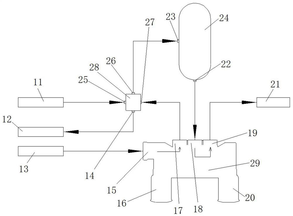
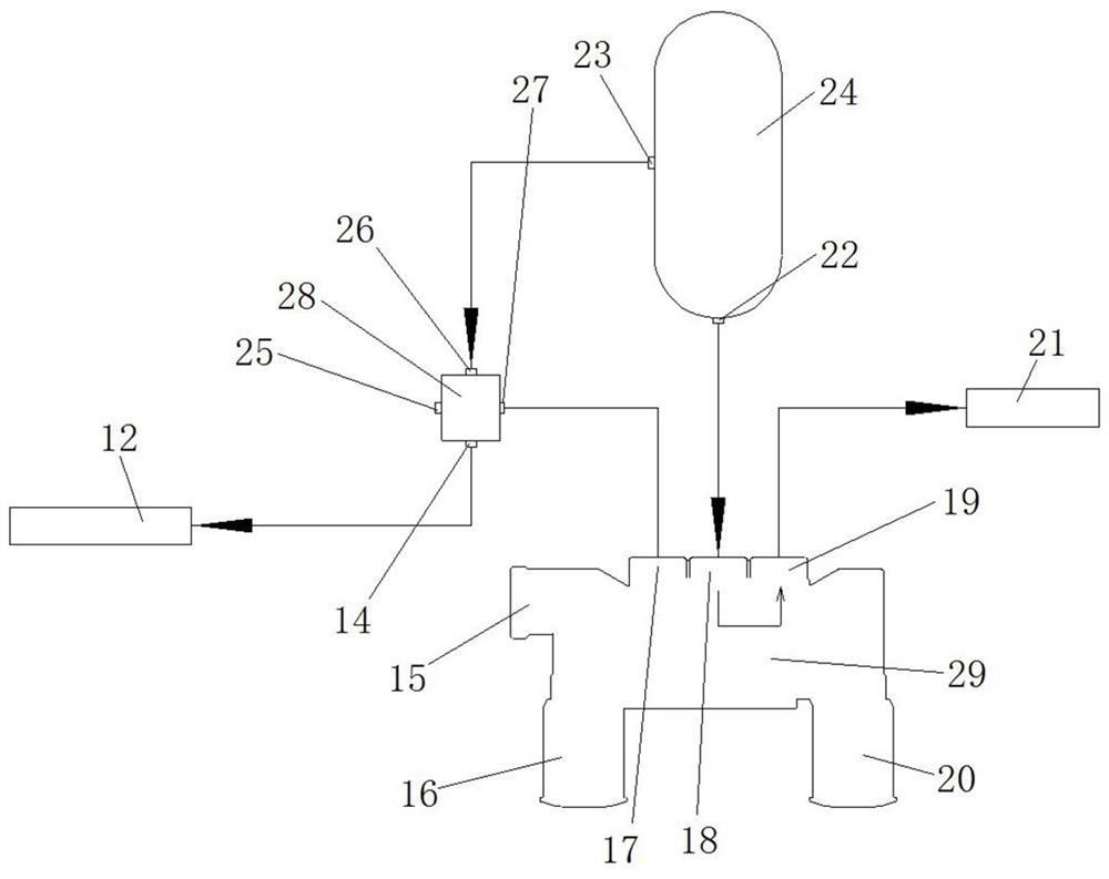
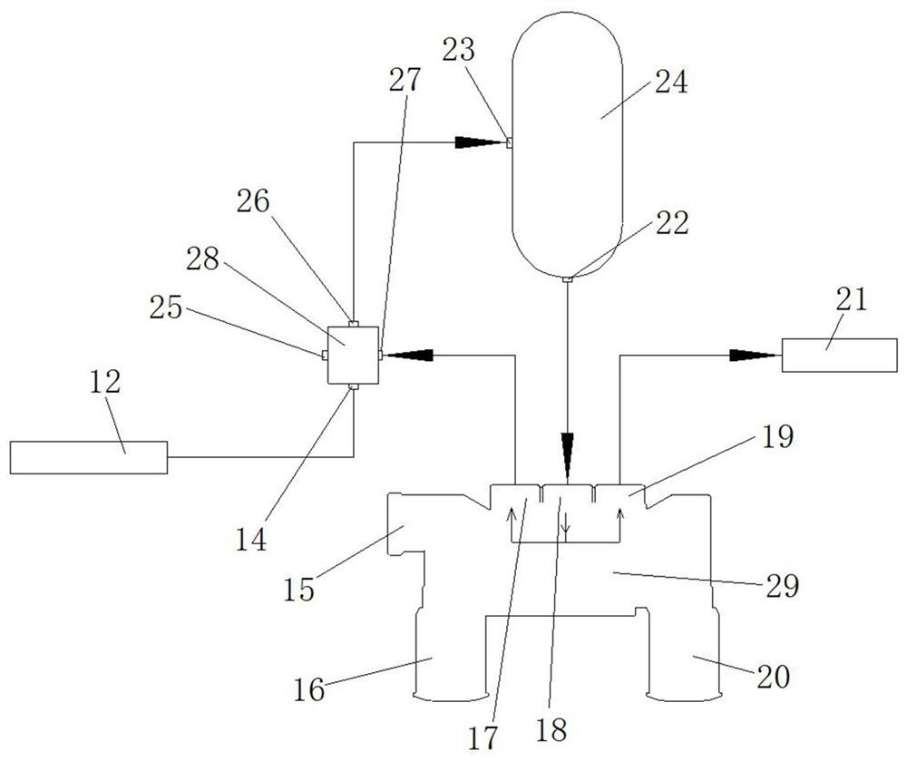
[0043] Such as figure 1 As shown, the drawbar trailer braking system includes an air storage container 24, a release valve 29 and an emergency relay valve 28. The air storage container 24 has a container air inlet 23 and a container air outlet 22, and the container air outlet 22 is arranged on the air storage container. One end of 24, container air inlet 23 is arranged on the middle part of gas storage container 24.
[0044] In this embodiment, the release valve 29 has a release valve inlet 15, a release valve outlet 17, a release valve interface 18, and a parking interface 19; the emergency relay valve 28 has a relay valve outlet 14, a first relay valve The air inlet 25 , the relay valve interface 26 and the second relay valve air inlet 27 . Wherein, the air storage container 24 is an air storage cylinder. In other embodiments, the gas storage container may be a gas bottle.
[0045]In this embodiment, the air inlet 15 of the release valve is in communication with the air s...
Embodiment 2
[0054] The difference between this embodiment and Embodiment 1 is that in Embodiment 1, the release valve 29 is provided with a moving button 16, and the connection between the release valve outlet 17 and the release valve interface 18 is realized through the moving button 16, so that the gas storage container The air pressure in 24 flows into the second relay valve air inlet 27 through release valve 29, to release the brake to drawbar trailer. In this embodiment, there is no moving button on the release valve. When the vehicle needs to be moved, re-connect the control pipeline of the tractor to the emergency relay valve, and connect the air supply pipeline of the tractor to the release valve. The air supply pipeline supplies air again to the air inlet 27 of the second relay valve through the release valve, so as to release the brake of the drawbar trailer.
Embodiment 3
[0056] The difference between this embodiment and Embodiment 1 is that in Embodiment 1, a parking button 20 is provided on the release valve 29, and when the parking button 20 cuts off the release valve interface 18 and the parking interface 19, the parking of the drawbar trailer is realized. Car; when the parking button 20 communicates the release valve interface 18 with the parking interface 19, the parking of the towbar trailer is released. In this embodiment, no parking button is provided on the release valve, the gas storage container is directly connected to the trailer parking pipeline, and a parking control valve is set on the trailer parking pipeline, and the parking control valve controls the disconnection of the trailer parking pipeline. When the parking control valve controls the connection of the trailer parking pipeline, the parking of the drawbar trailer is realized, and the parking of the drawbar trailer is released.
[0057] An embodiment of the drawbar traile...
PUM
 Abstract
Description
Claims
Application Information
 - R&D
- Intellectual Property
- Life Sciences
- Materials
- Tech Scout
- Unparalleled Data Quality
- Higher Quality Content
- 60% Fewer Hallucinations
Browse by: Latest US Patents, China's latest patents, Technical Efficacy Thesaurus, Application Domain, Technology Topic, Popular Technical Reports.
© 2025 PatSnap. All rights reserved.Legal|Privacy policy|Modern Slavery Act Transparency Statement|Sitemap|About US| Contact US: help@patsnap.com


