
Flow limiting device

A current-limiting device and current-limiting technology, applied in the field of sanitary products, can solve problems such as unsatisfactory flow range, expanded flow fluctuation range, large tolerance range, etc., and achieve high control accuracy, high water flow stability, and high water flow control Effect

Pending Publication Date: 2021-04-16
JOMOO KITCHEN & BATHROOM
View PDF0 Cites 0 Cited by
  • Summary
  • Abstract
  • Description
  • Claims
  • Application Information

AI Technical Summary

Problems solved by technology

Due to the large tolerance range of the O-ring during production, the flow range of 0.5L / MIN cannot be met after the test; and when the water passing area becomes smaller and the pressure remains constant, the water flow rate will increase and the flow fluctuation range will be further expanded.

Method used


Image

  • Flow limiting device
  • Flow limiting device
  • Flow limiting device

Examples


Embodiment Construction

[0022] Embodiments of the present invention will be described below with reference to the accompanying drawings. It should be noted that, in the case of no conflict, the embodiments of the present invention and the features in the embodiments can be combined arbitrarily with each other.

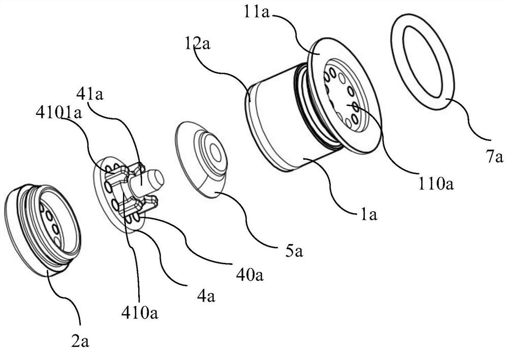
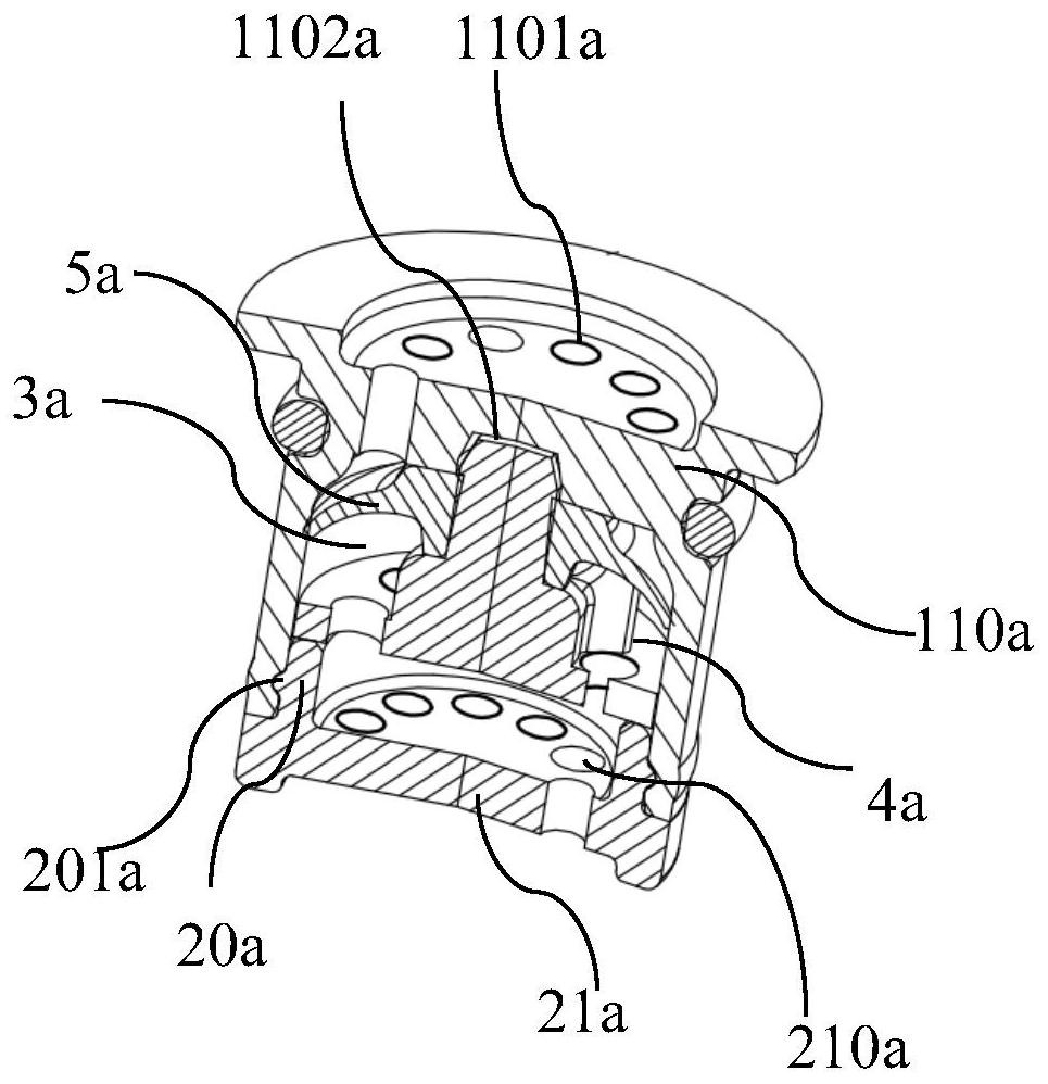
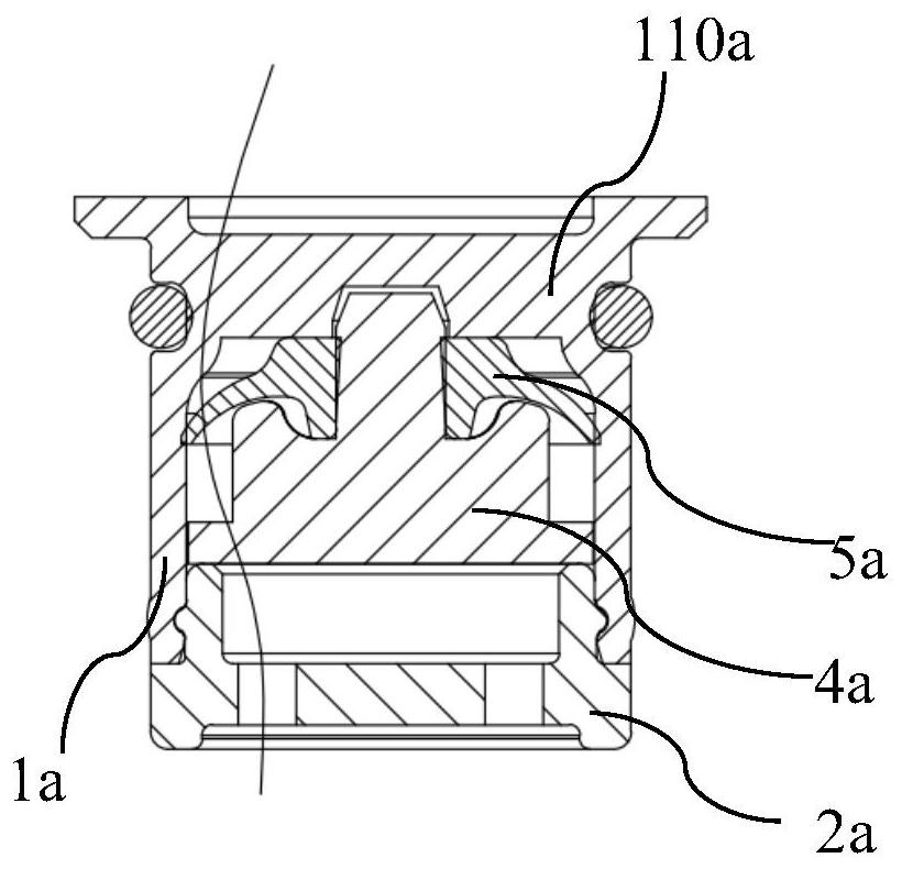
[0023] like Figure 1-3 As shown, Embodiment 1 of the present invention provides a current limiting device, comprising: a housing main body 1a, and a cover body 2a cooperating with the housing main body 1a. The housing main body 1a cooperates with the cover body 2a to form a water flow cavity 3a (refer to figure 2 ).

[0024] like figure 1 , figure 2 As shown, the housing body 1a includes a water inlet 11a, a water outlet 12a, and a cavity 13a disposed between the water inlet 11a and the water outlet 12a. The water inlet 11a is provided with a stop portion 110a, and the stop portion 110a is provided with a plurality of second flow holes 1101a arranged at intervals. A mounting groove 1...


PUM


Abstract

The embodiment of the invention discloses a flow limiting device which comprises a shell main body and a cover body matched with the shell main body for covering, and the shell main body and the cover body are matched to form a water flow cavity; the shell body is provided with a flow limiting structure in the water flow direction, a first speed limiting piece is arranged on the downstream of the flow limiting structure, the first speed limiting piece is arranged in the water flow cavity and divides the water flow cavity, the first speed limiting piece is provided with a plurality of first overflowing holes formed at intervals, and the first overflowing holes are communicated with the water flow cavity divided by the first speed limiting piece.

Description

technical field [0001] Embodiments of the present invention relate to but are not limited to the technical field of sanitary products, and more specifically, relate to a current limiting device. Background technique [0002] Currently, flow restrictors are widely used in water outlet devices to limit the outlet water flow of the water outlet device. In the prior art, Tongchang will add an O-ring in the flow channel of the flow limiting device, and the deformation of the O-ring will limit the water flow. When the water pressure increases, the O-ring will deform and be compressed. Flat, so that the cross-sectional area of ​​the water becomes smaller, so as to achieve the role of flow limitation. [0003] However, when the water pressure is lower than a certain value, the O-ring cannot be deformed, so that the current limiting effect cannot be achieved. At this time, if the O-ring is thickened to change the water passing area to achieve the current limiting effect, due to the ...

Claims


Application Information

Patent Timeline
IPC IPC(8): A47K3/28
Inventor 林孝发林孝山杜辉黄仕怀王飞虎
Owner JOMOO KITCHEN & BATHROOM
Learn More