Aquatic plant harvesting device
A technology for harvesting devices and aquatic plants, which is applied in the direction of harvesters, cutters, agricultural machinery and implements, etc. It can solve the problems of inconvenient collection of aquatic plants and inability to harvest in batches, so as to achieve free storage of the cutting mechanism, reduce redundant gaps, and save space Effect
- Summary
- Abstract
- Description
- Claims
- Application Information
AI Technical Summary
Problems solved by technology
Method used
Image
Examples
Embodiment 1
[0024] A waterweed harvesting device, such as figure 1 , figure 2 and image 3 As shown, it includes a hull 1, a motor 2, a waste chute 3, a rotating mechanism 4 and a cutting mechanism 5, a motor 2 is installed in the middle part of the upper side of the hull 1, a waste chute 3 is connected to the upper right side of the hull 1, and the left part of the hull 1 is provided with The turning mechanism 4 is provided with a cutting mechanism 5 between the left part of the hull 1 and the turning mechanism 4 .
[0025] When the user needs to cut aquatic plants, the device is first transported to the place where the aquatic plants are cut, the motor 2 is started, and the rotating mechanism 4 is driven to move, thereby driving the cutting mechanism 5 to move, to cut the aquatic plants, and to drive the cut aquatic plants to rotate and fall to the On the hull 1, the user can pick up aquatic plants from the hull 1, place them in the waste tank 3 for collection, fill them with aquatic...
Embodiment 2
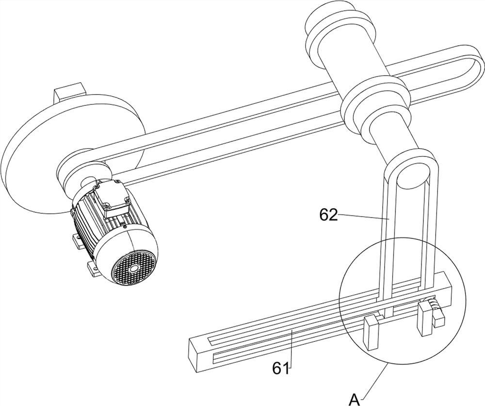
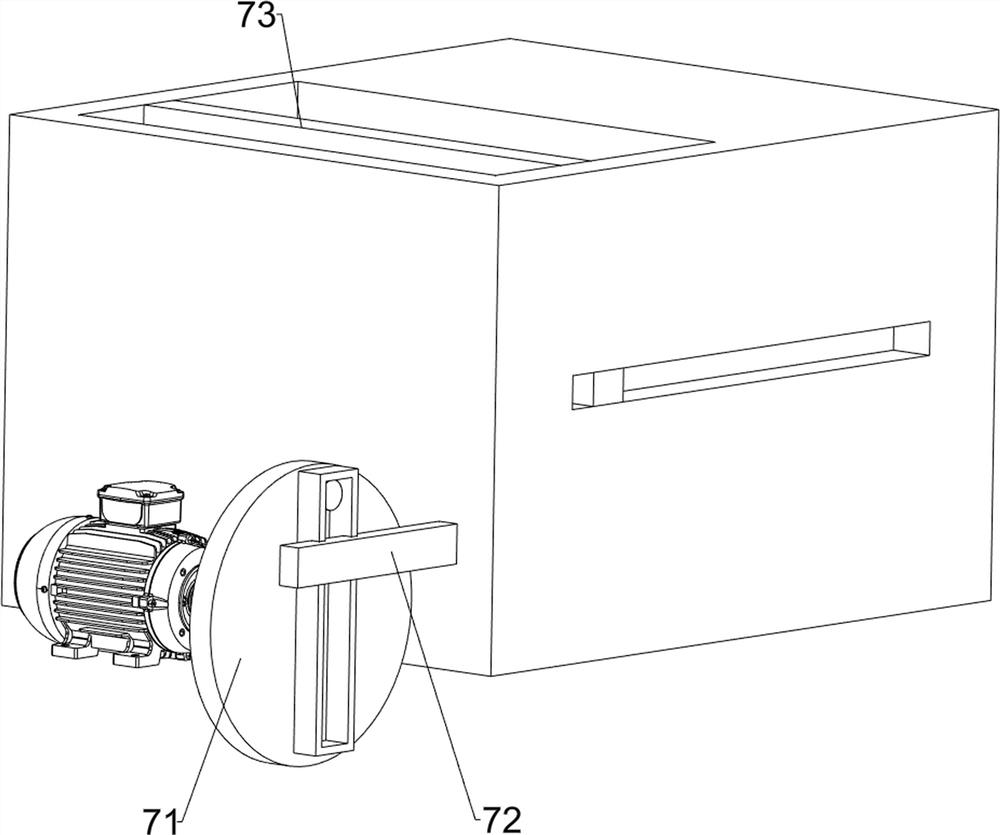
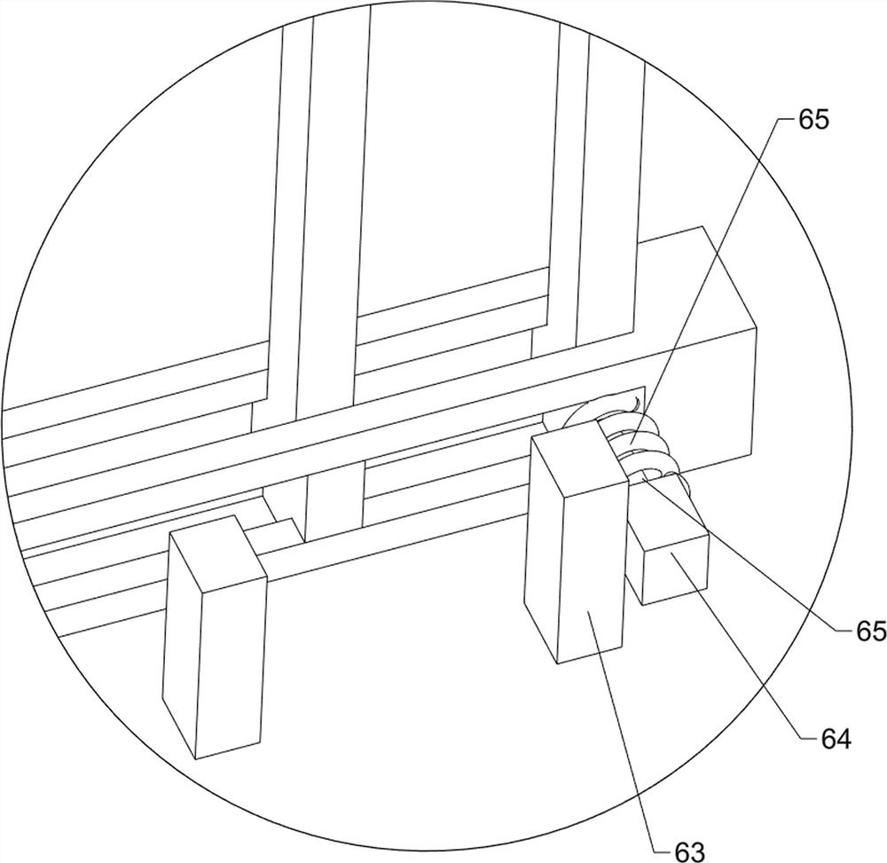
[0030] On the basis of Example 1, such as Figure 4 , Figure 5 and Figure 6 As shown, the height adjustment assembly 6 is also included, and the height adjustment assembly 6 includes a chute 61, a support rod 62, a block 63, a connecting block 64, a fifth connecting rod 65 and a spring 66. The side is connected with the first connecting rod 47, the front side of the third rotating shaft 46 is rotationally connected with the first connecting rod 47, the rear side of the upper part of the hull 1 is connected with a chute 61, and the chute 61 is slidably connected with a support rod 62 to support The upper part of the rod 62 is slidingly connected to the rear side of the fourth rotating shaft 48 on the right side, and the rear side of the upper part of the hull 1 is symmetrically connected with a stopper 63. The stopper 63 is located at the rear side of the chute 61, and the left rear side of the lower part of the support rod 62 is slidingly connected. There is a fifth connec...
PUM
 Abstract
Description
Claims
Application Information
 - R&D
- Intellectual Property
- Life Sciences
- Materials
- Tech Scout
- Unparalleled Data Quality
- Higher Quality Content
- 60% Fewer Hallucinations
Browse by: Latest US Patents, China's latest patents, Technical Efficacy Thesaurus, Application Domain, Technology Topic, Popular Technical Reports.
© 2025 PatSnap. All rights reserved.Legal|Privacy policy|Modern Slavery Act Transparency Statement|Sitemap|About US| Contact US: help@patsnap.com


