Combined type hydraulic control valve

A hydraulic control valve and combined technology, applied in the directions of servo motor components, fluid pressure actuating devices, mechanical equipment, etc., can solve the problems of commutation change, easy vibration or accidental touch, etc., and achieve safe and convenient use and scientific structure. reasonable effect

Inactive Publication Date: 2021-04-13
温州里洋精密机械有限公司
View PDF0 Cites 0 Cited by
  • Summary
  • Abstract
  • Description
  • Claims
  • Application Information

AI Technical Summary

Problems solved by technology

[0004] The purpose of the present invention is to provide a combined hydraulic control valve to solve the problem that the manual reversing valve proposed in the above background technology cannot lock the position after adjusting the reversing state, so that the reversing change is easily caused by vibration or accidental touch

Method used


Image

  • Combined type hydraulic control valve
  • Combined type hydraulic control valve
  • Combined type hydraulic control valve

Examples


Embodiment Construction

[0031]Next, the technical solutions in the embodiments of the present invention will be apparent from the embodiment of the present invention, and it is clearly described, and it is understood that the described embodiments are merely embodiments of the present invention, not all of the embodiments. Based on the embodiments of the present invention, there are all other embodiments obtained without making creative labor without making creative labor premises.

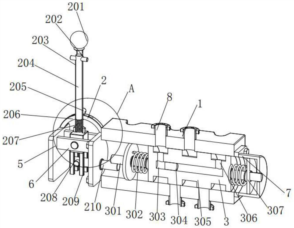
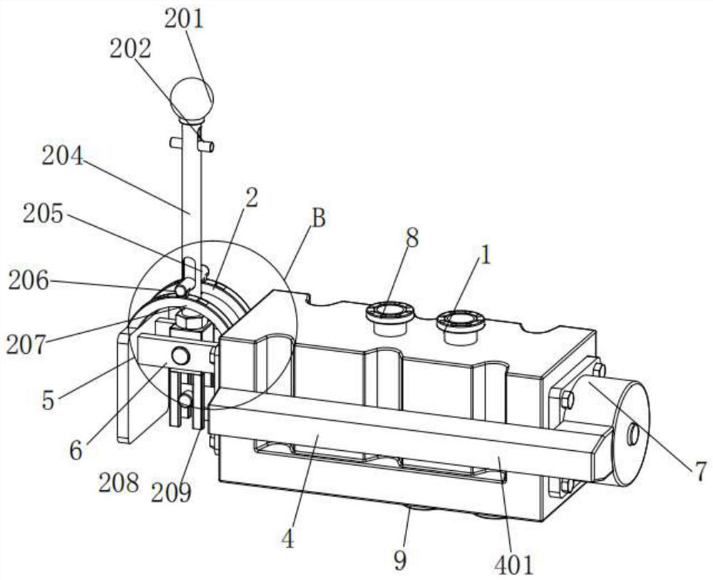
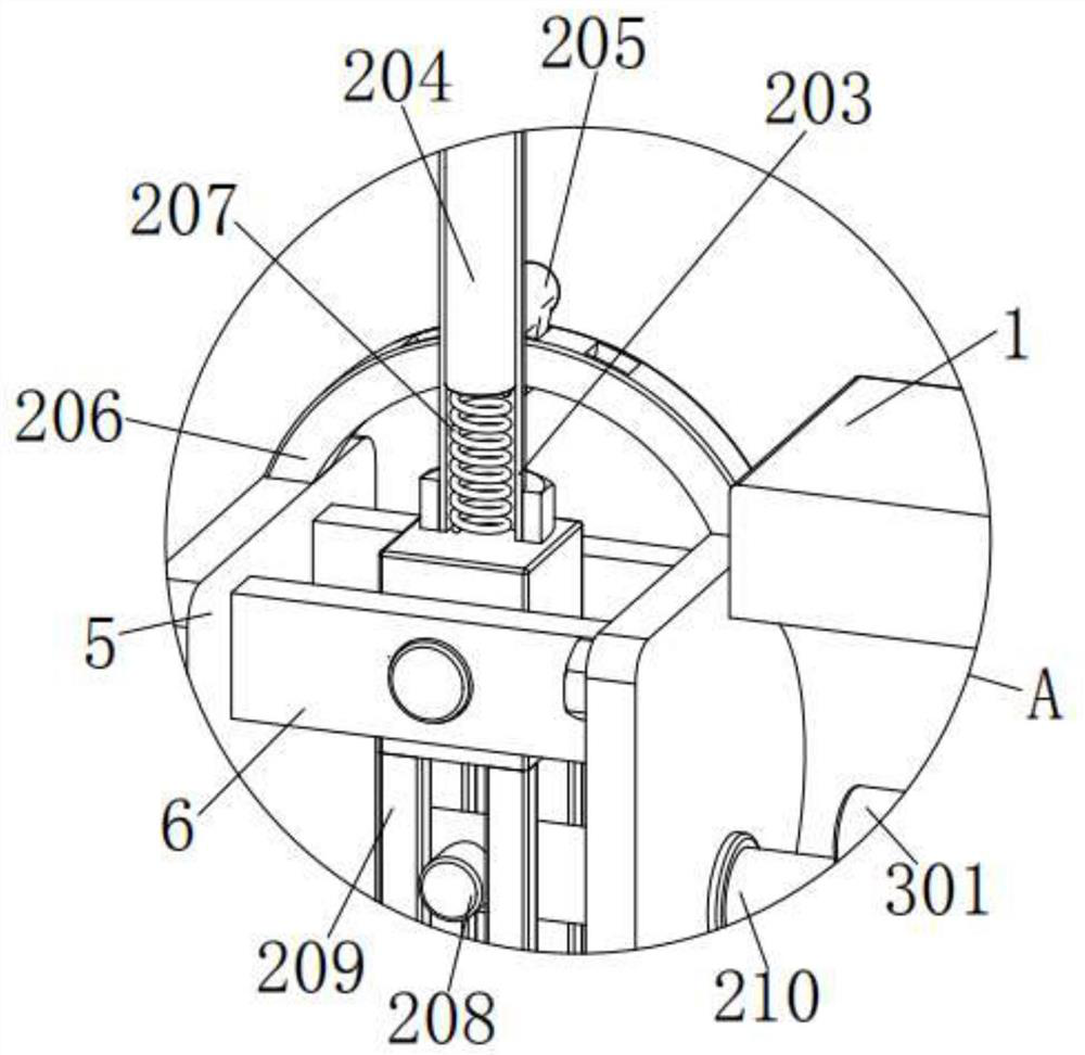
[0032]SeeFigure 1-7The present invention provides a technical solution: a combined hydraulic control valve comprising a vertical panel 5 and a cross plate 6, and both sides of the plurality of vertical plates 5 are fixed, and the horizontal plate 6 is fixed. The inner side is provided with a drive assembly 2, and the drive assembly 2 includes a spherical 201, a handle 202, a sleeve 203, a vertical rod 204, a block 205, an arc 206, a first spring 207, a rod 208, a vertical rod 209, and a first cross. The rod 210, the lower end out...


PUM


Abstract

The invention discloses a combined type hydraulic control valve. The combined type hydraulic control valve comprises vertical plates and transverse plates, the transverse plates are fixedly connected to the front sides and the rear sides of the upper portions of the inner ends of the multiple vertical plates, driving assemblies are arranged on the inner sides of the transverse plates, each driving assembly comprises a ball body, a handle, a sleeve, a vertical rod, a clamping block, an arc-shaped plate, a first spring, a round rod, a vertical rod and a first transverse rod, the round rods are connected to the inner sides of the left vertical rod and the right vertical rod in an attached mode, the first transverse rods are fixedly connected to the inner sides of the round rods, and the first transverse rods are slidably connected with the right end vertical plate. The combined type hydraulic control valve is scientific and reasonable in structure and safe and convenient to use, through cooperation of an oil inlet, the ball body, the handle, the vertical rod, the clamping block, the arc-shaped plate, the transverse plate and the sleeve, the clamping block is inserted into a groove of the arc-shaped plate again, oil liquid circulation control of the control valve is achieved, and the problem that an existing manual reversing valve cannot be locked after the reversing state is adjusted, and consequently reversing changes are prone to being caused by vibration or mistaken touch is solved.

Description

Technical field[0001]The present invention relates to the field of hydraulic control, and is specifically a combined hydraulic control valve.Background technique[0002]Hydraulic drive systems or hydraulic control systems are used to control components in liquid pressure, flow, and direction. The control pressure is referred to as a pressure control valve, and the flow rate is referred to as the flow control valve, the control pass, the break, and the flow direction are referred to as the direction control valve, and the manual commutation valve is used as a direction of frequent control valve, in hydraulic pressure In the reverse control, it is an indispensable, manual replacement valve, which has a multi-directional adjustable passage, which can change the fluid flow in a timely manner, although the existing manual replacement valve can achieve the flow direction of the fluid effect.[0003]However, prior art presence, the manual commutation valve cannot cause a problem that the lock ...

Claims


Application Information

Patent Timeline
Patent Type & Authority Applications(China)
IPC IPC(8): F15B13/02
CPCF15B13/02F15B2013/002
Inventor 沈建芳
Owner 温州里洋精密机械有限公司
Why Eureka
Try Eureka