Through hole forming equipment for PCB fixing base
A PCB board and forming equipment technology, applied in the field of through-hole forming equipment, can solve the problems of high operation risk, deviation of hole positions, and precise control of unfavorable punching positions, so as to improve accuracy, improve stability, and reduce labor costs Effect
- Summary
- Abstract
- Description
- Claims
- Application Information
AI Technical Summary
Problems solved by technology
Method used
Image

Examples
Embodiment 1
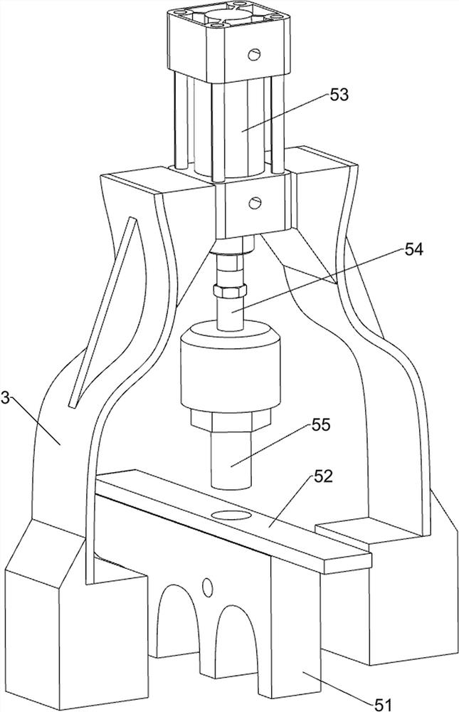
[0027] Such as figure 1 As shown, a through-hole forming equipment for PCB board fixing seat includes a base 1, a bracket 2, a gantry frame 3, a blanking mechanism 4, a punching mechanism 5 and a pushing mechanism 6, and the left side of the base 1 is provided with Support 2, a gantry 3 is provided on the left side of the support 2, a blanking mechanism 4 is provided on the top of the base 1, a punching mechanism 5 is provided in the middle of the gantry 3, and a pushing mechanism 6 is provided on the right side of the punching mechanism 5.
[0028] Aiming at the through-hole forming equipment for the PCB board fixing seat, this type of fixing seat achieves the effect of automatic blanking through the random grabbing mechanism of the continuous movement of the blanking mechanism 4, and then completes the through-hole forming process of the fixing seat through the punching mechanism 5 , during which the punching mechanism 5 moves up and down to drive the pusher mechanism 6 so t...
Embodiment 2
[0030] Such as figure 2 image 3 and Figure 4 As shown, on the basis of Embodiment 1, the unloading mechanism 4 includes a semicircular container 41, a rotating shaft 42, a crank wheel 43, an inclined block 44 and a handle 45, and the top of the base 1 is provided with a semicircular Container 41, the top of the semicircular container 41 is provided with a rotating shaft 42 through bearing rotation, the rotating shaft 42 is provided with a crank wheel 43, the upper left side of the semicircular container 41 has a through groove, and the through groove and the top of the support 2 are provided with The inclined block 44 and the rear end of the rotating shaft 42 are provided with a crank handle 45 .
[0031] For the through-hole forming equipment used for PCB board fixing seats, firstly, the staff puts a large number of fixing seats of this type into the semicircular container 41, and then drives the rotating shaft 42 to rotate by turning the handle 45, and the rotating shaf...
Embodiment 3
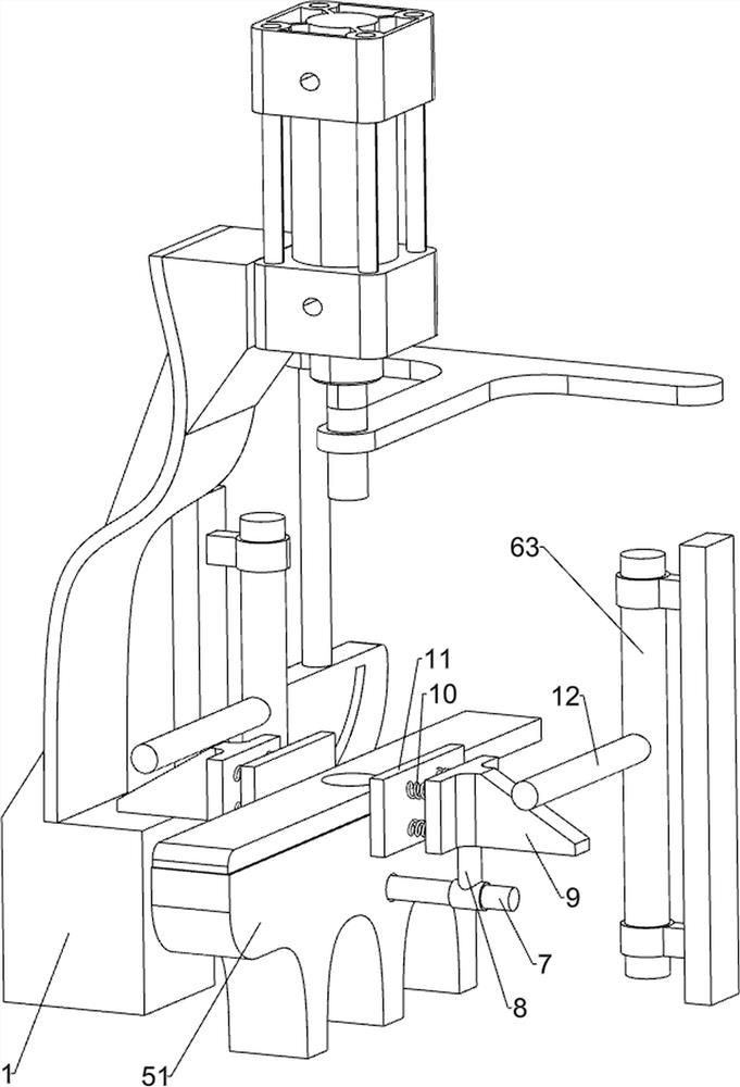
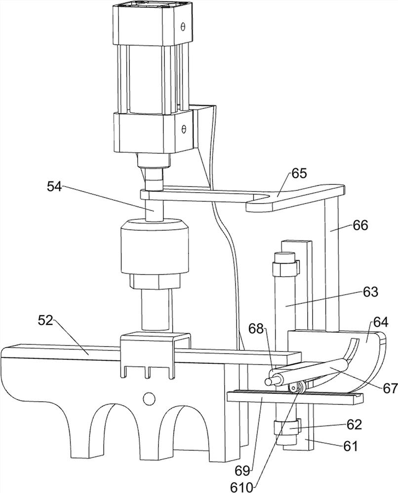
[0036] Such as Figure 5 Figure 6 Figure 7 As shown, on the basis of Embodiment 2, it also includes a second fixed rod 7, a first support rod 8, a wedge block 9, an elastic member 10, a pressure block 11 and a pressure rod 12, and the middle part of the cushion block 51 has a through hole. hole, the second fixed rod 7 is arranged in the through hole, the first support rod 8 is arranged on the top of the two ends of the second fixed rod 7 symmetrically sliding through the bushing, the top of the first support rod 8 is provided with a wedge block 9, and the wedge block 9 Four elastic parts 10 are evenly arranged around one side of the plane, and a pressing block 11 is arranged on the front side of the four elastic parts 10 , and a pressing bar 12 is arranged in the middle of the left side of the guide rod 63 .
[0037] The chute plate 64 reciprocates up and down in the guide sleeve 62 through the guide rod 63, and the guide rod 63 drives the pressure rod 12 to reciprocate up a...
PUM
 Abstract
Description
Claims
Application Information
 - Generate Ideas
- Intellectual Property
- Life Sciences
- Materials
- Tech Scout
- Unparalleled Data Quality
- Higher Quality Content
- 60% Fewer Hallucinations
Browse by: Latest US Patents, China's latest patents, Technical Efficacy Thesaurus, Application Domain, Technology Topic, Popular Technical Reports.
© 2025 PatSnap. All rights reserved.Legal|Privacy policy|Modern Slavery Act Transparency Statement|Sitemap|About US| Contact US: help@patsnap.com