Multi-path power supply circuit and power supply device
A technology of power supply circuit and multi-channel power supply, which is applied in circuit devices, emergency power supply arrangement, data switching current source, etc., can solve the problem that multi-channel power supply scheme cannot realize priority management of multi-channel power supply mode.
- Summary
- Abstract
- Description
- Claims
- Application Information
AI Technical Summary
Problems solved by technology
Method used
Image


Examples
no. 1 example
[0026] This embodiment provides a multi-channel power supply circuit to solve the problem that the existing multi-channel power supply scheme cannot implement priority management among multiple power supply modes, thereby setting the priority of multiple power supply modes and realizing preferential selection of adapters The external power supply is output by the power supply, followed by the external power supply output by the Ethernet POE power supply, and the third is the external power supply output by the USB input power supply; thus realizing reasonable management between POE power supply, adapter power supply and USB input power supply, and effective isolation Interaction of each power supply.
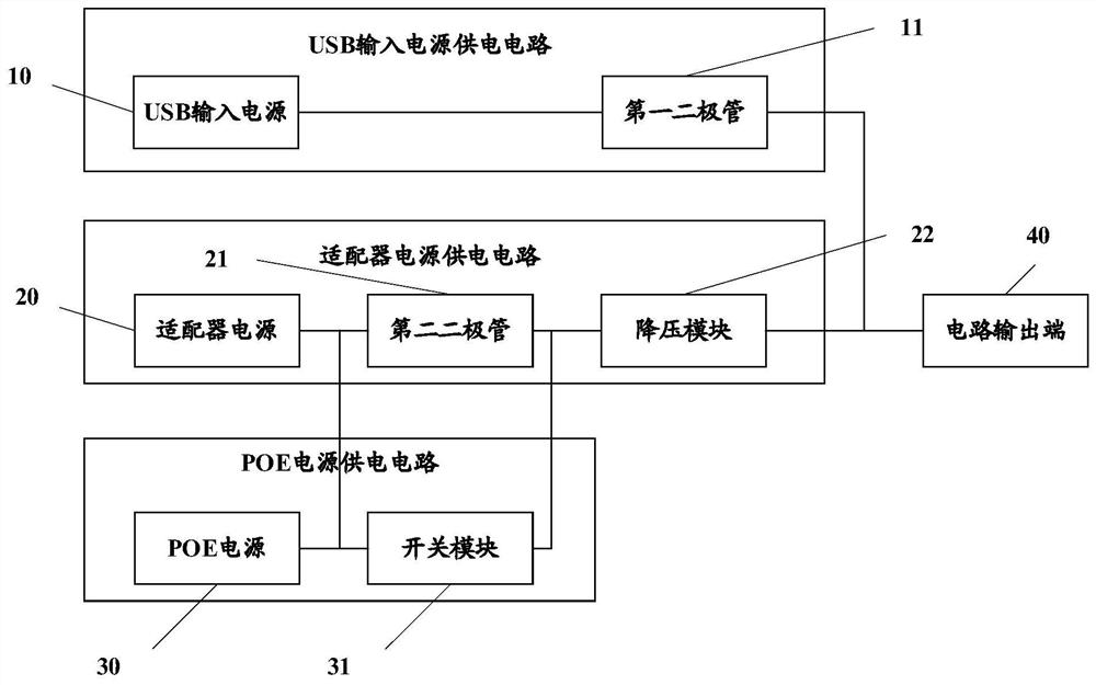
[0027] See figure 1 , a multi-channel power supply circuit provided by this implementation, including: a serial port bus USB input power supply circuit, an adapter power supply circuit, an Ethernet POE power supply circuit, and a circuit output terminal; wherein, the USB input p...
no. 2 example
[0038] This embodiment provides a schematic diagram of the circuit connection of a specific multi-channel power supply circuit, such as figure 2 As shown, the multi-channel power supply circuit includes: a USB input power supply circuit, an adapter power supply circuit, a POE power supply circuit, and a circuit output terminal.
[0039] Wherein, the USB input power supply circuit includes the input end of the USB input power supply, the pull-down resistor R100, and the diode VD1; the input end of the USB input power supply and the anode of the diode VD1 are connected to one end of the pull-down resistor R100, and the other end of the pull-down resistor R100 is grounded. The cathode of the diode VD1 is connected with the output terminal of the circuit.
[0040] Among them, the adapter power supply circuit includes the input end of the adapter power supply, pull-down resistor R100, diode VD1, capacitor C27, BUCK step-down module, power inductor L5, and diode VD5; the input end ...
no. 3 example
[0050] This embodiment provides a power supply device, and the power supply device includes the multi-channel power supply circuit in each of the above embodiments. The power supply device in this embodiment can provide 5V DC power for devices (such as base stations) in various application scenarios through a multi-channel power supply circuit. The specific structure of the multi-channel power supply circuit is as above, and will not be repeated here.
PUM
 Abstract
Description
Claims
Application Information
 - R&D
- Intellectual Property
- Life Sciences
- Materials
- Tech Scout
- Unparalleled Data Quality
- Higher Quality Content
- 60% Fewer Hallucinations
Browse by: Latest US Patents, China's latest patents, Technical Efficacy Thesaurus, Application Domain, Technology Topic, Popular Technical Reports.
© 2025 PatSnap. All rights reserved.Legal|Privacy policy|Modern Slavery Act Transparency Statement|Sitemap|About US| Contact US: help@patsnap.com