
An Injection Locking Method for Spaceborne High Energy Narrow Pulse Width Single Frequency Laser

An injection-locking, high-energy technology that is applied in the field of lasers to achieve good energy stability, reduce jitter, and reduce time errors.

Active Publication Date: 2022-02-01
BEIJING RES INST OF TELEMETRY +1
View PDF10 Cites 0 Cited by
  • Summary
  • Abstract
  • Description
  • Claims
  • Application Information

AI Technical Summary

Problems solved by technology

[0005] The present invention aims to solve the problem that space lasers output high-stability, high-energy single-frequency pulse lasers in harsh environments, and provides a new injection locking method. The locking controller predicts the peak value of the resonance signal according to the resonance signal fed back by the photodetector. , and give the synchronous signal of the amplifier power supply and the trigger signal of the Q switch, and the output energy stability is better than 0.5% of the high-energy single-frequency pulse laser of the order of 100 millijoules

Method used


Image

  • An Injection Locking Method for Spaceborne High Energy Narrow Pulse Width Single Frequency Laser
  • An Injection Locking Method for Spaceborne High Energy Narrow Pulse Width Single Frequency Laser
  • An Injection Locking Method for Spaceborne High Energy Narrow Pulse Width Single Frequency Laser

Examples


Embodiment 1

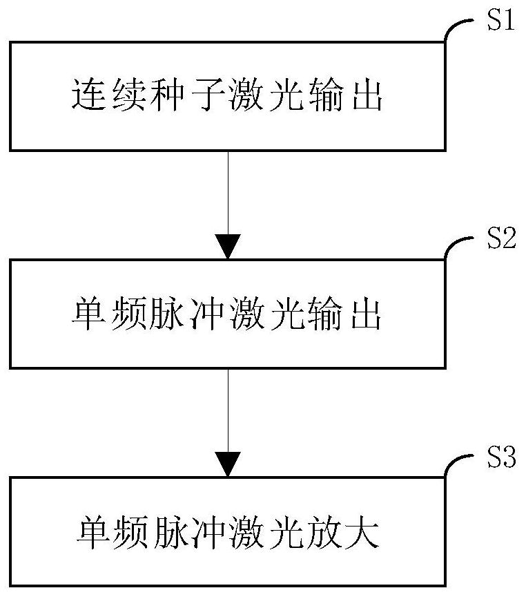
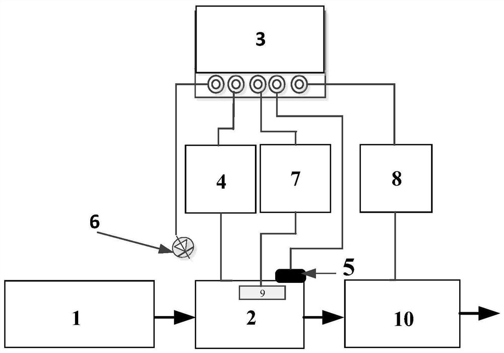
[0033] Such as Figure 1-2 As shown, an injection locking method for a spaceborne high-energy narrow-pulse width single-frequency laser is characterized in that: comprising the following steps:

[0034] S1. Continuous seed laser output: the seed laser 1 outputs the seed laser to the oscillator 2, the injection lock controller 3 outputs the synchronization signal to the oscillator power supply 4, and the oscillator power supply 4 starts to supply power to the oscillator 2;

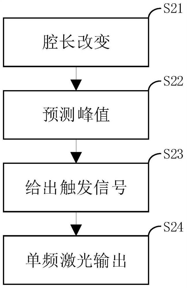
[0035] S2. Single-frequency pulse laser output: the injection lock controller 3 outputs a triangular wave voltage to control the reciprocating motion of the piezoelectric ceramic 5, the oscillator 2 changes the cavity length during the movement of the piezoelectric ceramic 5, and the photodetector 6 detects the oscillator 2 The resonant signal is fed back to the injection-locked controller 3, and the injection-locked controller 3 judges the peak value of the resonant signal and predicts the moment when the ...

Embodiment 2

[0038] Such as Figure 1-2 As shown, an injection locking method for a spaceborne high-energy narrow-pulse width single-frequency laser is characterized in that: comprising the following steps:

[0039] S1. Continuous seed laser output: seed laser 1 outputs 1064nm single-frequency continuous laser of fundamental transverse mode and single longitudinal mode as seed laser to oscillator 2, injection locking controller 3 outputs synchronization signal to oscillator power supply 4, oscillator power supply 4 Start powering Oscillator 2;

[0040] S2. Single-frequency pulse laser output: the injection lock controller 3 outputs a triangular wave voltage to control the reciprocating motion of the piezoelectric ceramic 5, the oscillator 2 changes the cavity length during the movement of the piezoelectric ceramic 5, and the photodetector 6 detects the oscillator 2 The resonant signal is fed back to the injection-locked controller 3, and the injection-locked controller 3 judges the peak v...


PUM

PropertyMeasurementUnit
wavelengthaaaaaaaaaa

Abstract

The invention provides an injection locking method for a space-borne high-energy narrow pulse width single-frequency laser, using pulse pumping and seed injection locking technology, and the injection locking controller predicts the peak value of the resonance signal according to the resonance signal fed back by the photodetector, and The synchronous signal of the power supply of the amplifier and the trigger signal of the Q switch are given, which reduces the time error of the opening of the Q switch and reduces the jitter of the energy output. The invention solves the problem of high-stability frequency locking of a satellite-borne nanosecond-level narrow pulse width laser, and can realize high-energy single-frequency pulse laser output with stronger anti-interference ability and better energy stability.

Description

technical field [0001] The invention relates to the technical field of lasers, in particular to an injection locking method for a spaceborne high-energy narrow-pulse-width single-frequency laser. Background technique [0002] Space-borne direct wind measurement lidar and space-borne hyperspectral lidar can detect global three-dimensional wind field and cloud-aerosol, which is of great significance for accurate weather forecast and battlefield environment protection. Both space-borne direct wind measurement lidar and space-borne hyperspectral lidar require the laser used to be a single-frequency pulse laser, and at the same time require the laser to output a laser with a high energy stability of the order of 100 millijoules. [0003] There are two main technical methods to realize single-frequency pulsed laser: seed injection locking technology and seed chopper amplification technology. The seed injection locking technology is to inject a single-frequency, continuous seed li...

Claims


Application Information

Patent Timeline
Patent Type & Authority Patents(China)
IPC IPC(8): H01S3/094H01S3/098
CPCH01S3/1109H01S3/094076
Inventor 赵一鸣叶青李静周永升姜国庆于勇李凉海高明伟
Owner BEIJING RES INST OF TELEMETRY
Learn More