Biomass particle combustion furnace

A biomass particle and combustion furnace technology, which is applied in household stoves/stoves, solid heating fuel, lighting and heating equipment, etc., can solve the problem of not being able to reduce the slag of biomass particles, and achieve the effect of the best utilization rate

Pending Publication Date: 2021-04-09
王景春
View PDF6 Cites 0 Cited by
  • Summary
  • Abstract
  • Description
  • Claims
  • Application Information

AI Technical Summary

Problems solved by technology

The shortcoming of this invention is that can not reduce the situation that biomass pellet falls off slag

Method used


Image

  • Biomass particle combustion furnace
  • Biomass particle combustion furnace
  • Biomass particle combustion furnace

Examples


specific Embodiment approach 1

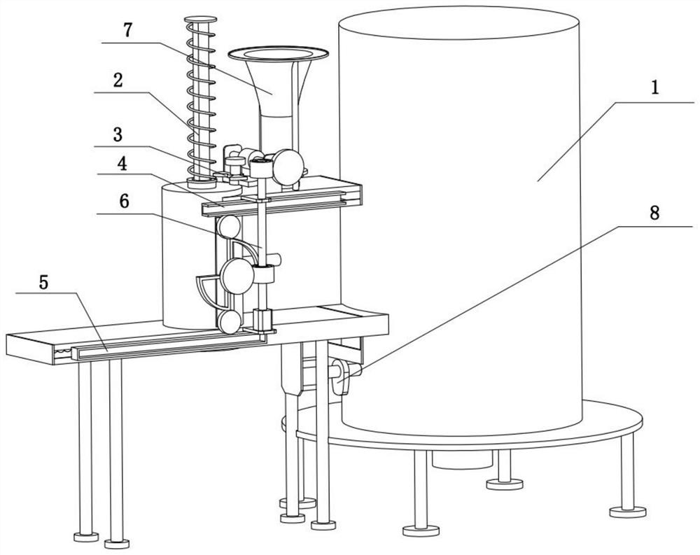
[0032]Bonded belowFigure 1-10In the present embodiment, the biomass particle combustion furnace includes a housing assembly 1, a compression assembly 2, a transmission assembly 3, a feed assembly 4, a discharge assembly 5, a drive assembly 6, a carrier assembly 7, and a feed combustion assembly 8. The compression assembly 2 is slidably coupled to the housing assembly 1, and the transmission assembly 3 rotates on the housing assembly 1, the compression assembly 2 and the transmission assembly 3 mesh the transmission, the feed assembly 4 slides on the housing assembly 1, out The material assembly 5 is slidably connected to the lower end of the housing assembly 1, and the drive assembly 6 is fixed to the housing assembly 1, the transmission assembly 3 and the drive assembly 6 mesh the transmission, the feed assembly 4 and the discharge assembly 5 mesh with the drive assembly 6. The carrier assembly 7 is fixed to the housing assembly 1, the carrier assembly 7 and the drive assembly 6 me...

specific Embodiment approach 2

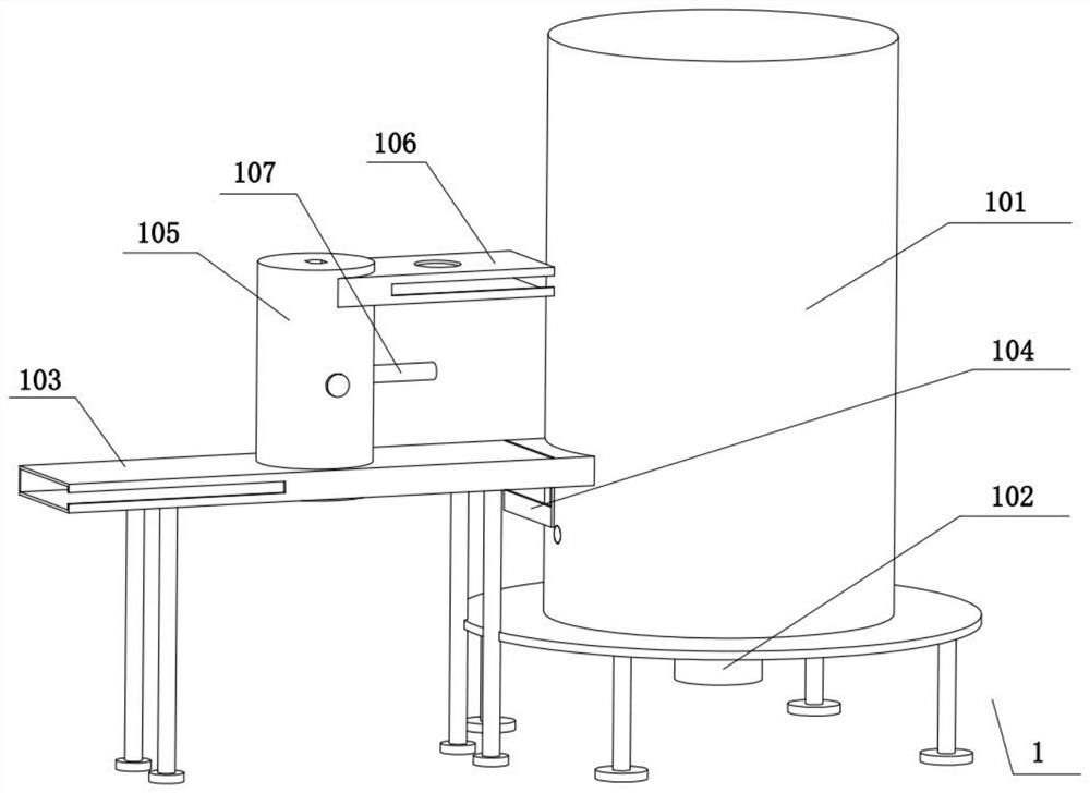
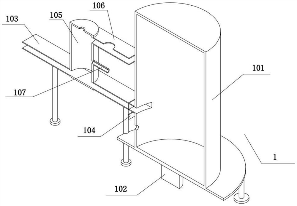
[0035]Bonded belowFigure 1-10In the present embodiment, the housing assembly 1 includes a combustion furnace 101, a ignition mechanism 102, a lower slide 103, a feed baffle 104, a shaped bucket 105, a bundle 106, and a connecting tube 107, and a lower end fixed connection of the combustion furnace 101. There is a ignition mechanism 102, and the lower slide 103 is fixed to the combustion furnace 101, and the add baffle 104 slides on the lower sliding track 103, and the shaped bucket 105 is fixed to the lower slide 103, and the upper slide 106 is fixed to the shaped bucket 105 The upper end is fixed to the connection tube 107 on the molded bucket 105.

specific Embodiment approach 3

[0037]Bonded belowFigure 1-10In the present embodiment, the compression assembly 2 includes a pressure type plate 201, a waist-type threaded rod 202, a threaded pipe gear 203, a spring plate 204, and a reset spring 205, and the shaped plate 201 is slidably connected to the molded bucket 105, a pressure type plate Fixed lumbar thread rod 202, the threaded pipe gear 203 is rotated on the shaped bucket 105, and the lumbar threaded rod 202 and the threaded pipe gear 203 are rotated by the threaded drive, and the spring plate 204 rotates on the threaded pipe gear 203, waist The upper end of the thread rod 202 and the spring plate 204 are fixed to the reset spring 205.


PUM


Abstract

The invention relates to the technical field of combustion furnace equipment, in particular to a biomass particle combustion furnace. The biomass particle combustion furnace has the advantage of being capable of reducing slag falling of biomass particles and comprises a shell assembly, a compression assembly, a transmission assembly, a feeding assembly, a discharging assembly, a driving assembly, a material carrying assembly and a material adding combustion assembly. The compression assembly is slidably connected to the shell assembly, the compression assembly is rotatably connected to the shell assembly, the compression assembly is in meshing transmission with the transmission assembly, the feeding assembly is slidably connected to the shell assembly, the discharging assembly is slidably connected to the lower end of the shell assembly, the driving assembly is fixedly connected to the shell assembly, and the transmission assembly is in meshing transmission with the driving assembly. The feeding assembly and the discharging assembly are both in meshing transmission with the driving assembly, the material carrying assembly is fixedly connected to the shell assembly, the material carrying assembly is in meshing transmission the driving assembly, and the material adding combustion assembly is connected to the shell assembly.

Description

Technical field[0001]The present invention relates to the technical field of combustion furnace equipment, and more specifically is a biomass particle combustion furnace.Background technique[0002]The invention disclosed is a biomass particle combustion furnace which is uniformly distributed and high combustion efficiency is disclosed. Including the storage bin, feed bin, and combustion warehouse, the standby bin being a V-shaped structure, fixed to the top of the feed bin, the combustion bin fixedly connected to the feed bin, the bin Near The bonding warehouse is provided with a discharge port; the bottom plate of the distribution bin is tilted downward, the biomass particles move through the direction of the inclined bottom plate to the direction of the burning bin; the bottom plate is provided with an adarable feed The plate, the feed plate moves in the tilt direction of the bottom plate by a straight drive mechanism. The linear drive mechanism includes a cylinder, an electric pus...

Claims


Application Information

Patent Timeline
IPC IPC(8): F24B1/00F24B13/04
CPCF24B1/00F24B13/04
Inventor 王景春
Owner 王景春
Why Eureka
Try Eureka