
Casing for aero-engine and machining method of casing

A technology of aero-engines and casings, which is applied to engine components, machines/engines, mechanical equipment, etc., and can solve problems such as unfavorable maintenance and replacement of aero-engine casings, collision damage between aero-engines and casings, and easy deformation of parts during processing. problems, to achieve the effect of simple structure, avoid deformation and prolong service life

Pending Publication Date: 2021-04-09
株洲丰发精工实业有限公司
View PDF0 Cites 2 Cited by
  • Summary
  • Abstract
  • Description
  • Claims
  • Application Information

AI Technical Summary

Problems solved by technology

[0002] Aeroengine is a highly complex and precise thermodynamic machine. As the heart of an aircraft, it is not only the driving force for aircraft flight, but also an important driving force to promote the development of aviation industry. Generally, aeroengines need to be fixed when they are installed; traditional aeroengines The structure of the casing is complex and troublesome to use. It is generally fixed by screws, which is extremely unstable and troublesome to install and disassemble. The impact damage of the aero-engine and the casing is caused, and the casing of the traditional aero-engine is directly processed by a lathe, which can easily cause deviations in the processing of the casing, and the parts are easily deformed during processing, and the internal stress cannot be eliminated, causing the parts to be distorted and deformed; in response to these defects, It is necessary to design a casing used in an aero-engine and its processing method

Method used


Image

  • Casing for aero-engine and machining method of casing
  • Casing for aero-engine and machining method of casing
  • Casing for aero-engine and machining method of casing

Examples


Embodiment Construction

[0036] The following will clearly and completely describe the technical solutions in the embodiments of the present invention with reference to the accompanying drawings in the embodiments of the present invention. Obviously, the described embodiments are only some, not all, embodiments of the present invention. Based on the embodiments of the present invention, all other embodiments obtained by persons of ordinary skill in the art without making creative efforts belong to the protection scope of the present invention.

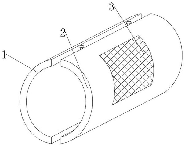
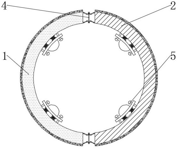
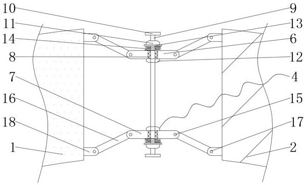
[0037] see Figure 1-5 , the present invention provides a technical solution: a casing used in an aero-engine, including a first casing shell 1, a second casing casing 2, a casing heat dissipation net 3, an adjustment assembly 4, a fixing assembly 5, and a heat insulation pad 29 and an anti-corrosion pad 30, the first casing shell 1 side is provided with the second casing casing 2, the first casing casing 1 and the second casing casing 2 are bonded with a ther...


PUM


Abstract

The invention discloses a casing for an aero-engine and a machining method of the casing. The casing comprises a first casing shell, a second casing shell, a casing heat dissipation net, adjusting assemblies, fixing assemblies, a heat insulation pad and an anti-corrosion pad, wherein casing heat dissipation nets are arranged on the outer sides of the first casing shell and the second casing shell correspondingly, the adjusting assemblies are arranged in the center of the first casing shell and the center of the second casing shell, and a plurality of fixing assemblies are arranged inside the first casing shell and the second casing shell. The casing for the aero-engine and the machining method of the casing are simple in structure and convenient to operate, a traditional screw fixing mode is abandoned, clamping fixing is adopted, fixing is firmer, installing and uninstalling are convenient, a user can maintain and replace the aero-engine conveniently, the distance between the first casing shell and the second casing shell can be freely adjusted, the casing for the aero-engine and the machining method of the casing are suitable for installing and fixing aero-engines of different sizes and wide in application range.

Description

technical field [0001] The invention relates to the technical field of casings of aero-engines, in particular to casings used in aero-engines and a processing method thereof. Background technique [0002] Aeroengine is a highly complex and precise thermodynamic machine. As the heart of an aircraft, it is not only the driving force for aircraft flight, but also an important driving force to promote the development of aviation industry. Generally, aeroengines need to be fixed when they are installed; traditional aeroengines The structure of the casing is complex and troublesome to use. It is generally fixed by screws, which is extremely unstable and troublesome to install and disassemble. The impact damage of the aero-engine and the casing is caused, and the casing of the traditional aero-engine is directly processed by a lathe, which can easily cause deviations in the processing of the casing, and the parts are easily deformed during processing, and the internal stress cannot...

Claims


Application Information

Patent Timeline
Patent Type & Authority Applications(China)
IPC IPC(8): F01D25/24F01D25/14B23P15/00
CPCF01D25/24F01D25/243F01D25/14B23P15/00
Inventor 苏文宏陈蓁黎明
Owner 株洲丰发精工实业有限公司
Learn More