Pressure regulating chamber device for hydropower station

A technology for surge chambers and hydropower stations, which is applied in hydropower stations, hydropower, water conservancy projects, etc. It can solve problems affecting structural safety, water hammer pressure loss, and general energy dissipation effects, so as to improve the mechanical performance of structures and reduce Water hammer pressure, avoiding the effect of excessive local pressure

Active Publication Date: 2021-04-09
河南省水利第二工程局集团有限公司
View PDF11 Cites 1 Cited by
  • Summary
  • Abstract
  • Description
  • Claims
  • Application Information

AI Technical Summary

Problems solved by technology

[0002] The surge chamber structure is a commonly used pressure regulating and stabilizing device in hydropower stations. Due to the long pressure pipes of hydropower stations, once the unit shuts down in an emergency or suddenly reduces the opening, it is easy to generate a certain amount of water hammer pressure in the pressure pipes, and the water hammer pressure exceeds the pressure of the hydropower station. When the pipeline is allowed to stress, it will cause damage to the pressure pipeline and cause safety hazards
[0003] When controlling the water hammer pressure of the pressure pipeline of the hydropower station, it is often used to prolong the shutdown start-stop time of the unit, and to increase the strength of the pressure pipeline, etc. The structure of the surge chamber is an important engineering measure to effectively reduce the water hammer pressure. The pipe is connected to the pressure pipe, its energy dissipation effect is average, the water hammer pressure cannot be consumed in time, and the large water hammer pressure will still affect the structural safety

Method used


Image

  • Pressure regulating chamber device for hydropower station
  • Pressure regulating chamber device for hydropower station
  • Pressure regulating chamber device for hydropower station

Examples


specific Embodiment approach

[0016]DETAILED DESCRIPTION OF THE INVENTION: The structure defined by the present invention will be specifically explained in the following description.

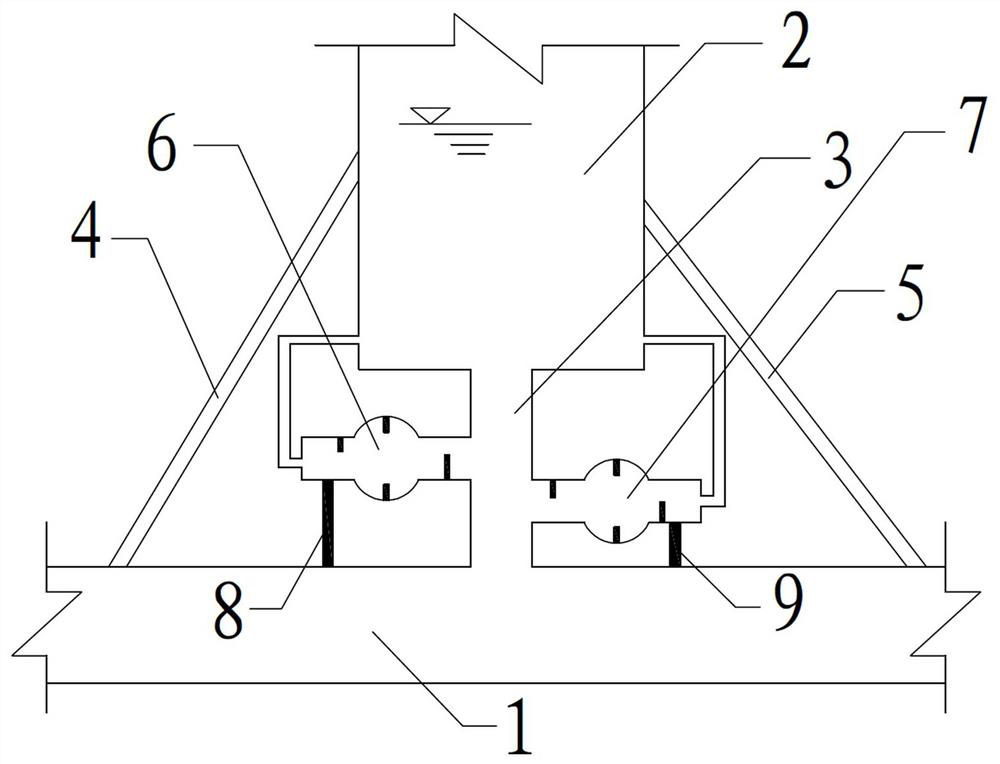
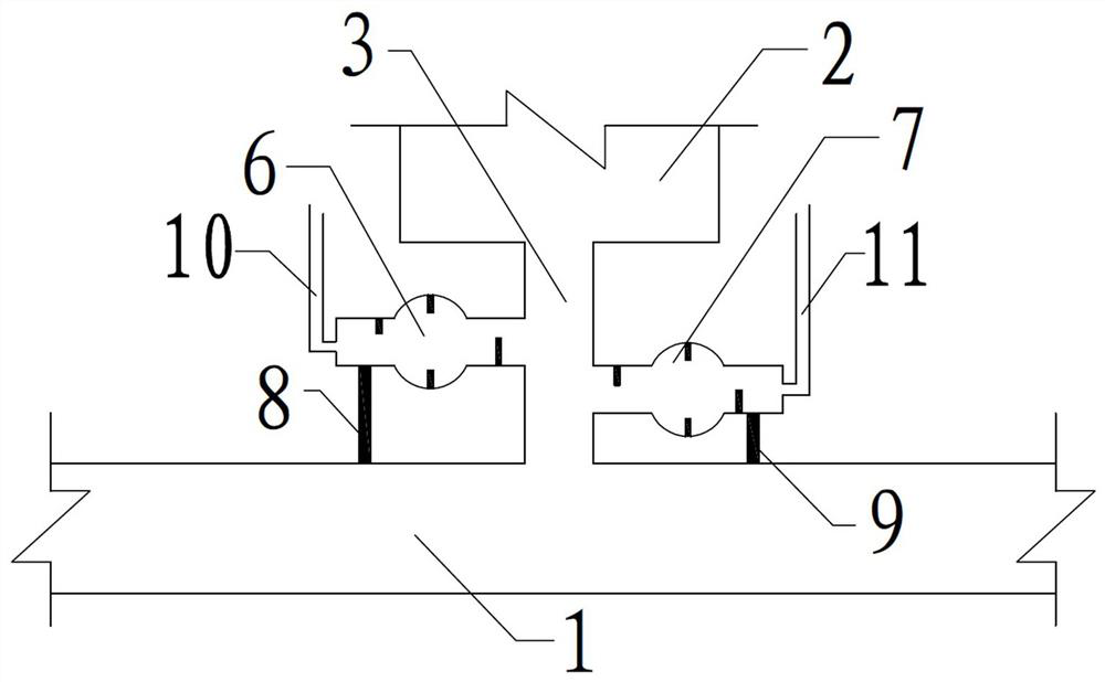
[0017]The present invention provides a pressure relief chamber 2 apparatus for a hydropower station, and the hydropower station is provided, and the pressure conduit 1 is provided with a pressure regulating chamber 2, and the voltage pressure chamber 2 and the pressure conduit 1 pass through the first connection. The pipe 3 is connected, and the left support rod 4 and the right support rod 5 are provided on the pressure conduit 1, wherein the left support rod 4 is located on the left side of the pressure regulating chamber 2, and the right support rod 5 is located at the pressure regulating chamber. On the side, the lower end of the left support rod 4 is fixedly coupled to the pressure conduit 1, and the upper end of the left support rod 4 is fixedly coupled to the pressure regulating chamber 2, and the lower end of the right support...


PUM


Abstract

The invention provides a pressure regulating chamber device for a hydropower station. By arranging a left supporting rod and a right supporting rod, the stress performance of a pressure regulating chamber is improved; by arranging a left branch pipe and a right branch pipe, effective buffering of the pressure regulating chamber structure and a pressure pipeline is achieved, and the water hammer pressure is reduced; and protruding sections are arranged in the left branch pipe and the right branch pipe, a plurality of vertical plates are arranged in the left branch pipe and the right branch pipe correspondingly, effective buffering of the water hammer pressure is achieved, and the pressure regulating and stabilizing performance of the pressure regulating chamber is further improved. The structure is simple, construction is easy, and the working performance of the pressure regulating chamber can be remarkably improved.

Description

Technical field[0001]The present invention relates to the field of water conservancy engineering, and more particularly to a pressure regulating chamber device for hydropower stations.Background technique[0002]The pressure regulating chamber structure is a pressure regulating regulator, which is commonly used in hydropower stations. Since the hydropower station is long, once the unit emergency stop or suddenly reduces the opening degree, it is easy to generate a certain water shock pressure in the pressure pipe, and the hydrotential pressure exceeds the hydropower station pressure. When the pipe is allowed to stress, it will cause damage to the pressure pipeline, causing safety hazards.[0003]When the pressure of the hydropower pipe pressure pipeline is controlled, there is a multi-use extension unit to turn off the start and stop, and increase the strength of pressure pipeline, the pressure regulating room structure is an important engineering measures that effectively reduce the pr...

Claims


Application Information

Patent Timeline
Patent Type & Authority Applications(China)
IPC IPC(8): E02B9/00E02B9/06
CPCE02B9/00E02B9/06Y02E10/20
Inventor 侯占强王伟黄兴豹赵志峰刘冲张贝宜胡心勇王桂玉李国兴徐康舒
Owner 河南省水利第二工程局集团有限公司
Why Eureka
Try Eureka