
Computed tomography device

A tomography, computer technology, applied in the direction of CT scanner, diagnosis, echo tomography, etc., can solve the problems of limited angle of CT scan, unstable transportation, etc.

Pending Publication Date: 2021-04-09
HARBIN INST OF PHYSICAL EDUCATION
View PDF0 Cites 0 Cited by
  • Summary
  • Abstract
  • Description
  • Claims
  • Application Information

AI Technical Summary

Problems solved by technology

[0005] Aiming at the deficiencies of the prior art, the present invention provides a computerized tomography device, which solves the problems of the limitation of the angle of the computerized tomography and the unstable transportation

Method used


Image

  • Computed tomography device
  • Computed tomography device
  • Computed tomography device

Examples


Embodiment 1

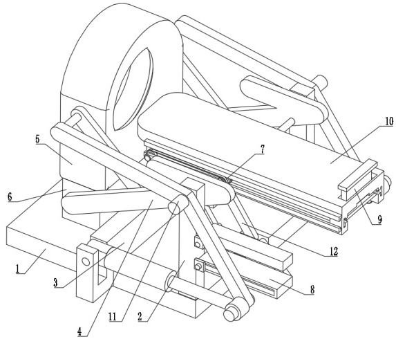
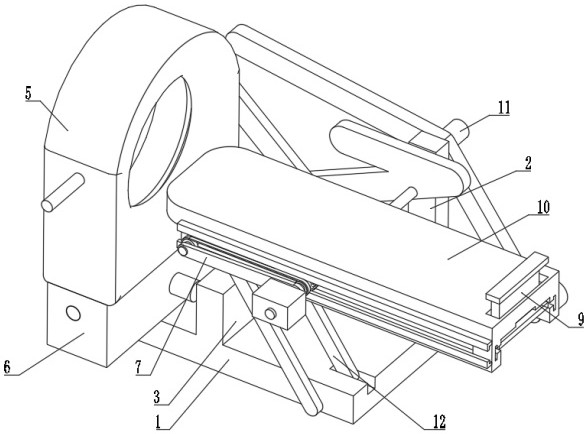
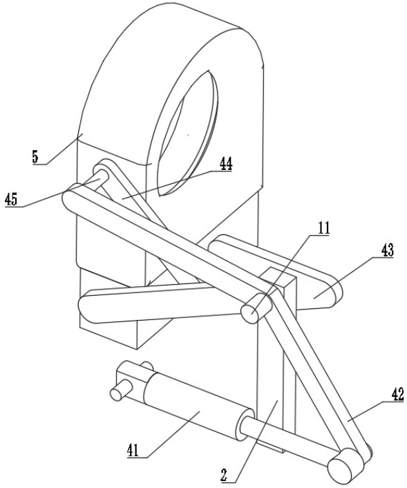
[0035] see Figure 1-6 , a computed tomography device, comprising a support base plate 1, the upper surface of the support base plate 1 is respectively welded with a fixed frame 2 and a connecting seat 3, the connecting seat 3 is located on the left side of the fixed frame 2, and the inside of the fixed frame 2 is connected with a rotating shaft 11. The surface of the rotating shaft 11 is provided with an adjustment mechanism 4, the surface of the adjustment mechanism 4 is provided with a CT machine body 5, the bottom of the CT machine body 5 is provided with a lifting mechanism 6, the right side of the fixed frame 2 is provided with a pedal mechanism 8, and the adjustment mechanism A bed frame 10 is provided on the surface of 4, a support device 9 is provided inside the bed frame 10, and a conveying mechanism 7 is provided on the surface of the adjustment mechanism 4.

[0036] In this embodiment, two support rods 12 are fixedly connected to the upper surface of the support ba...

Embodiment 2

[0043] see Figure 7-8 , the pedal mechanism 8 includes an upper pedal 81, the front portion of the upper pedal 81 is rotatably connected to the surface of the rotating support plate 42, the rear portion of the rotating support plate 42 is welded with a sliding pin 84, and the surface of the sliding pin 84 is slidingly connected with the lower pedal 82 , the front portion of lower pedal 82 offers limit groove 85, and slide pin 84 is positioned at the inside of limit groove 85, and the surfaces of upper pedal 81 and lower pedal 82 are all rotatably connected to the surface of fixed mount 2, and the rear portion of upper pedal 81 rotates Connecting plate 83 is connected, and the bottom of connecting plate 83 is rotatably connected to the rear portion of lower pedal 82. By being provided with pedal mechanism 8, when scanning in the lying mode, the two pedals are in a parallel state, and the user can step on the upper pedal 81 and the lower pedal. The pedal 82 is used as a step to...


PUM


Abstract

The invention relates to the technical field of tomography, and discloses a computed tomography device. The computed tomography device comprises a supporting bottom plate, wherein a fixing frame and a connecting seat are welded to the upper surface of the supporting bottom plate, a rotating shaft is rotationally connected to the interior of the fixing frame, an adjusting mechanism is arranged on the surface of the rotating shaft, a lifting mechanism is arranged at the bottom of a CT machine body, a pedal mechanism is arranged on the right side of the fixing frame, a bed frame is arranged on the surface of the adjusting mechanism, and a supporting device is arranged in the bed frame. According to the computed tomography device, the contraction of two hydraulic oil cylinders is controlled, then two rotating supporting plates are driven to rotate around the center of the rotating shaft, then the CT machine body and the bed frame are driven to carry out synchronous angle switching adjustment, so that the angle of the whole scanning is adjusted and changed, the tomography can be conveniently carried out in different areas and different ranges, the scanning process is more comprehensive, the situation of scanning omission is reduced, and the overall applicability of the equipment is improved.

Description

technical field [0001] The invention relates to the technical field of tomography, in particular to a computer tomography device. Background technique [0002] Computed tomography, also known as computerized tomography, is a diagnostic imaging examination. This scanning technology has been widely used to examine the human body and form image data for doctors to diagnose. Usually, computerized tomography equipment includes multiple subsystems Each subsystem is provided with a plurality of different components that work together to complete the scanning and imaging of the human body. [0003] At present, in the process of using computerized tomography, most of the equipment is horizontal or vertical, and it cannot switch the angle, which leads to certain limitations in the process of scanning the body, resulting in the diagnosis of diseases. , the scanning is not comprehensive enough, and in the process of transporting the user, the transport is unstable and shaking, so a com...

Claims


Application Information

Patent Timeline
IPC IPC(8): A61B6/03A61B6/04
CPCA61B6/032A61B6/035A61B6/04A61B6/0407
Inventor 宋杨
Owner HARBIN INST OF PHYSICAL EDUCATION
Learn More