Eureka AIR delivers breakthrough ideas for toughest innovation challenges, trusted by R&D personnel around the world.

Structural health monitoring network

a technology of health monitoring and structural health, applied in the direction of error detection/correction, digital computer details, instruments, etc., can solve the problems of inability to scale to suit larger lack of flexibility, and inability to meet the needs of large-scale or more complex applications, etc., to facilitate the scanning of the structure

Inactive Publication Date: 2010-06-24
ACELLENT TECH
View PDF43 Cites 26 Cited by
  • Summary
  • Abstract
  • Description
  • Claims
  • Application Information

AI Technical Summary

Benefits of technology

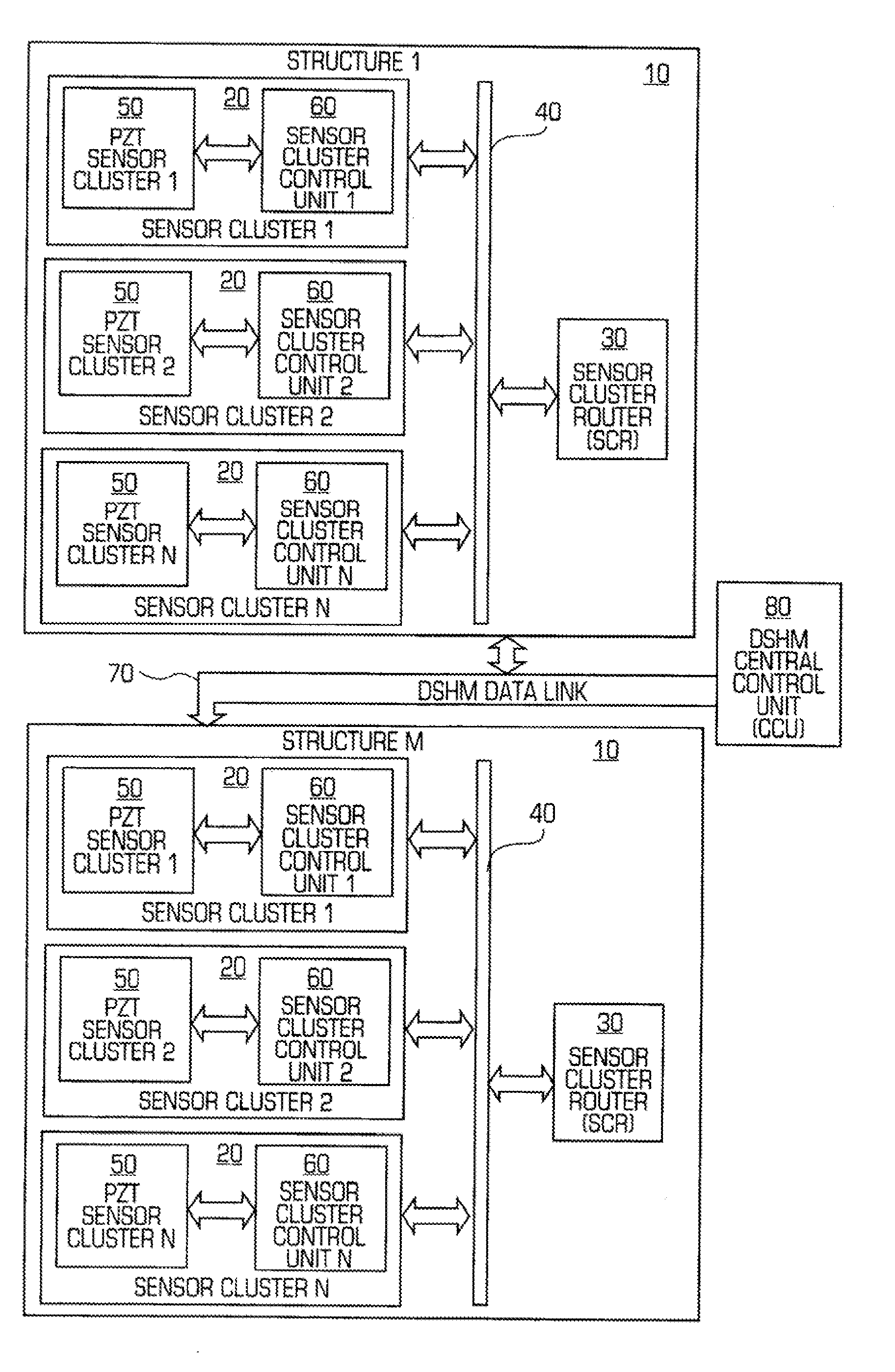
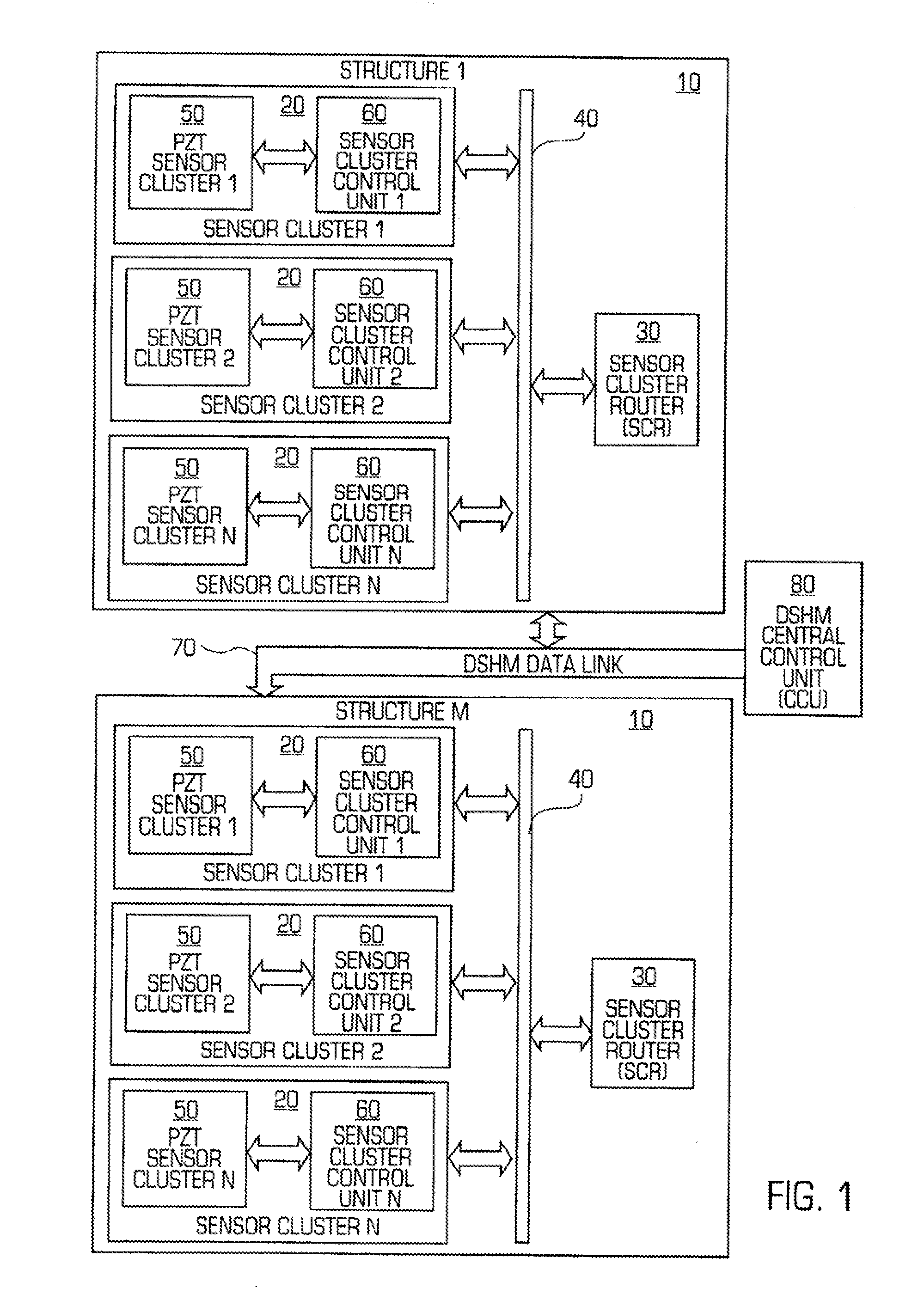
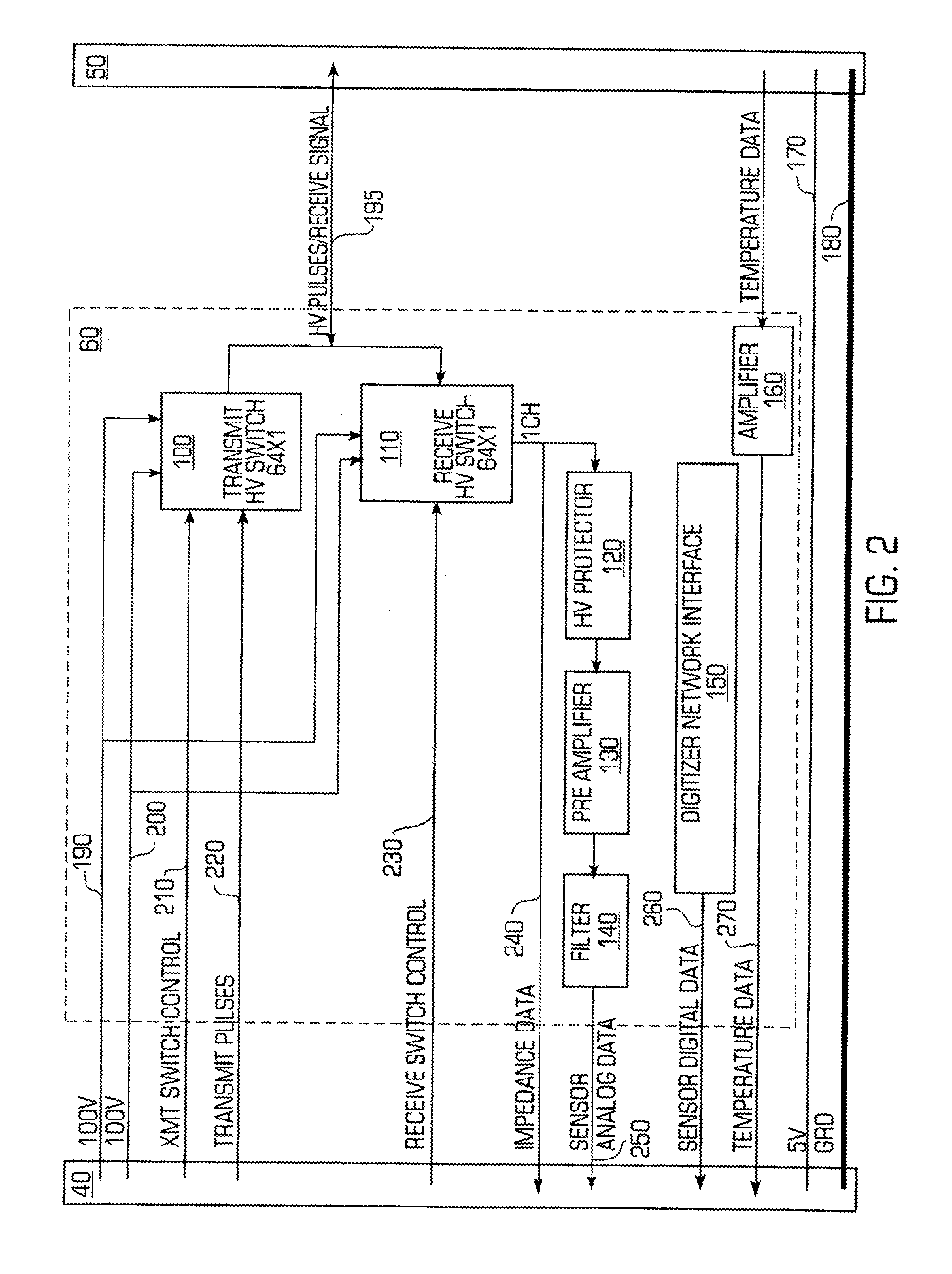
[0006]In one embodiment, a structural health monitoring system comprises a plurality of monitoring clusters, each monitoring cluster having a plurality of monitoring elements each configured to monitor the health of a structure, and a cluster controller in communication with the plurality of monitoring elements and configured to control an operation of the plurality of monitoring elements. The system also includes a data bus in communication with each monitoring cluster of the plurality of monitoring clusters. Furthermore, the cluster controllers are each configured to receive from the data bus control signals for facilitating the control of the monitoring elements, and to transmit along the data bus data signals from the monitoring elements.

Problems solved by technology

However, these systems are not without their disadvantages.
While such systems can be effective for certain applications, they lack flexibility and are often incapable of scaling to suit larger or more complex applications.
For instance, a single controller is often unsuitable for controlling the number of monitoring elements (e.g., sensors, actuators, etc.) required to monitor large structures.

Method used


Image

  • Structural health monitoring network
  • Structural health monitoring network
  • Structural health monitoring network

Examples


Embodiment Construction

[0036]In one embodiment of the invention, monitoring elements such as sensors and actuators are configured as a network, with groups of monitoring elements each controlled by a local controller, or cluster controller. A data bus interconnects each cluster controller with a router, forming a networked group of “monitoring clusters” connected to a router. In some embodiments, the router identifies particular clusters, and sends commands to the appropriate cluster controllers, specifying certain monitoring elements and instructing the cluster controllers to carry out the appropriate monitoring operations with those elements. Data returned from the monitoring elements is sent to the cluster controllers, which then pass the information to the router.

[0037]The invention also includes embodiments in which each such network (i.e., a group of monitoring clusters and their associated router) is linked over a common data line to a central controller. That is, the central controller is set up t...


PUM


Abstract

A networked configuration of structural health monitoring elements. Monitoring elements such as sensors and actuators are configured as a network, with groups of monitoring elements each controlled by a local controller, or cluster controller. A data bus interconnects each cluster controller with a router, forming a networked group of “monitoring clusters” connected to a router. In some embodiments, the router identifies particular clusters, and sends commands to the appropriate cluster controllers, instructing them to carry out the appropriate monitoring operations. In turn, the cluster controllers identify certain ones of their monitoring elements, and direct them to monitor the structure as necessary. Data returned from the monitoring elements is sent to the cluster controllers, which then pass the information to the router. Other embodiments employ multiple sensor groups directly connected to a central controller, perhaps with distributed local control elements. Methods of operation are also disclosed.

Description

[0001]This application is a continuation-in-part of U.S. patent application Ser. No. 11 / 543,185, filed on Oct. 3, 2006, the entire contents of which are hereby incorporated by reference.BRIEF DESCRIPTION OF THE INVENTION[0002]This invention relates generally to structural health monitoring. More specifically, this invention relates to structural health monitoring networks.BACKGROUND OF THE INVENTION[0003]Current structural health monitoring systems are designed to carry out diagnostics and monitoring of structures. As such, they typically confer many advantages, such as early warning of structural failure, and detection of cracks or other problems that were previously difficult to detect.[0004]However, these systems are not without their disadvantages. For example, many current structural health monitoring systems are relatively simple systems that have a number of sensors connected to a single controller / monitor. While such systems can be effective for certain applications, they la...

Claims


Application Information

Patent Timeline
Patent Type & Authority Applications(United States)
IPC IPC(8): G06F15/00
CPCG01N29/2475G01N2291/0258H04L67/125H04L43/0817G01N2291/106
Inventor QING, XINLINBENERJEE, SOURAVZHANG, CHANGBEARD, SHAWNLI, IRENECHANG, FU-KUO
Owner ACELLENT TECH
Why Eureka
Eureka Blog
Learn More