
A fault location device for transmission line inspection

A technology for power transmission lines and positioning devices, applied in fault locations, cable installation, cable installation devices, etc., can solve the problems of manpower consumption, inconvenience for next use, aging, etc., and achieve good repair effect.

Active Publication Date: 2022-05-24
海南电网有限责任公司琼海供电局
View PDF0 Cites 0 Cited by
  • Summary
  • Abstract
  • Description
  • Claims
  • Application Information

AI Technical Summary

Problems solved by technology

[0002] With the continuous acceleration of economic development, the number of kilometers of distribution network in Hainan is increasing, and the total amount of distribution overhead lines has been greatly increased. Since the transmission lines are used outdoors, after long-term use of the transmission lines, the insulation outside the transmission lines Aging will occur in the local part of the layer, which will reduce the effect of insulation and isolation current leakage at this place, resulting in a large leakage during the transmission process, which will affect the normal transmission function of the transmission line
Therefore, it is necessary to monitor and deal with the fault points on the transmission line; the traditional method of determining the fault interval is often manual line inspection, which consumes a lot of manpower and easily increases the burden of line inspection for maintenance personnel. In order to solve this problem , some manufacturers have invented a fault point patrol device, which inspects the transmission line through an ultrasonic detector, and then quickly determines the location of the fault point, and controls the glue filling component to fill the local position of the aging insulation layer to improve the The insulation effect at the location, but the above-mentioned fault point inspection device has the following deficiencies: one is to directly add a layer of insulating glue on the outer surface of the fault of the insulation layer, and the insulation effect is not ideal; There will be glue left to block the outlet, which is not convenient for next use

Method used

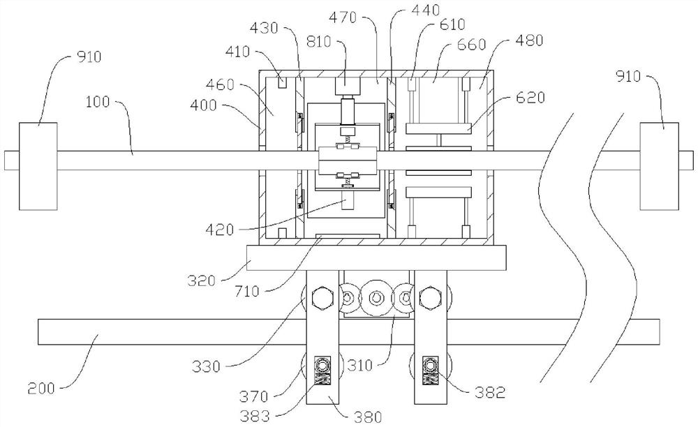
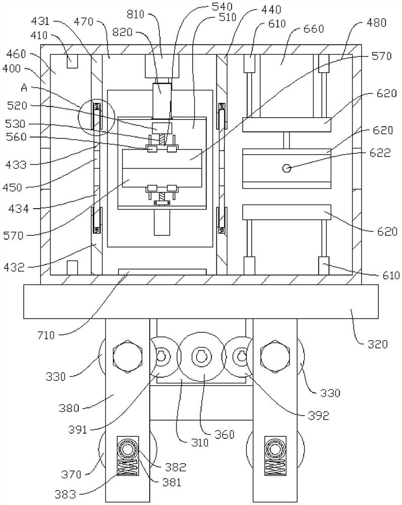
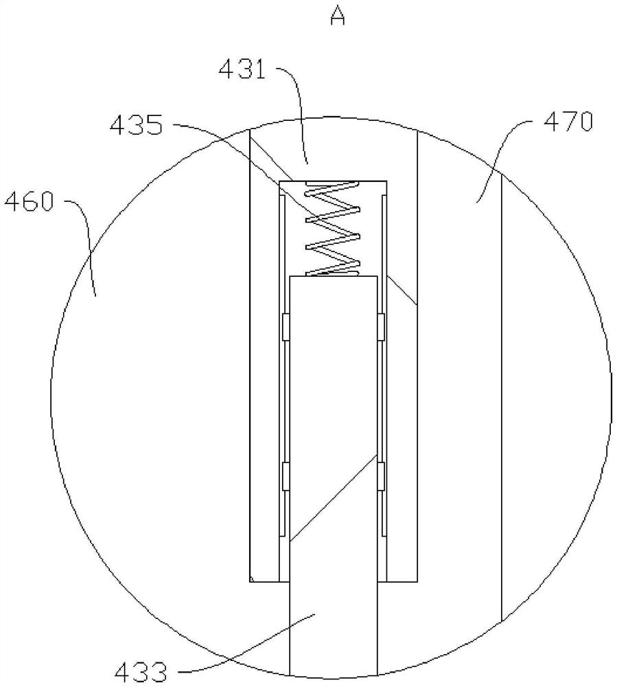

Image

  • A fault location device for transmission line inspection
  • A fault location device for transmission line inspection
  • A fault location device for transmission line inspection

Examples


Embodiment Construction

[0041] This part will describe the specific embodiments of the present invention in detail, and the preferred embodiments of the present invention are shown in the accompanying drawings. Each technical feature and overall technical solution of the invention should not be construed as limiting the protection scope of the invention.

[0042] In the description of the present invention, it should be understood that the orientation or positional relationship indicated by "up", "down", "front", "rear", "left", "right", etc. The orientation or positional relationship shown in the drawings is only for the convenience of describing the present invention and simplifying the description, rather than indicating or implying that the indicated device or element must have a specific orientation, be constructed and operated in a specific orientation, and therefore cannot be understood as Limitations of the present invention.

[0043] In the description of the present invention, if there is ...


PUM


Abstract

The invention provides a fault point location device for transmission line inspection, which is used to detect transmission lines, which includes current detection boxes respectively arranged at both ends of the transmission line; guide rods are arranged on the front and rear sides of the transmission line, and belt There is a moving mechanism for a box with an ultrasonic detector inside; the inner wall of the box is located on one side of the ultrasonic detector and is provided with an arc-shaped groove; the arc-shaped groove is slidably connected with a sliding plate with a first screw rod arranged up and down, the first The upper and lower parts of the screw with opposite rotation directions are respectively provided with a first moving block and a second moving block, the first moving block and the second moving block are connected with mounting seats, and the sides of the two mounting seats facing each other are provided with semicircular grooves , the left and right ends of each semicircular groove are respectively provided with vertical arc knives, and a horizontal cutter is provided between the two vertical arc knives; one side of the sliding plate is provided with a glue replenishing mechanism. The present invention removes the insulation layer at the aging place on the transmission line through the cooperation of the horizontal cutting knife and the vertical arc knife, and then replenishes the insulating glue to the aging place, and the repairing effect is good.

Description

technical field [0001] The invention relates to the field of power transmission line faults, in particular to a fault point locating device for power transmission line inspection. Background technique [0002] With the continuous acceleration of economic development, the number of kilometers of Hainan's distribution network has continued to increase, and the total amount of overhead distribution lines has increased significantly. Since the transmission lines are used outdoors, after long-term use of the transmission lines, the insulation outside the transmission lines The local position of the layer will be aged, so that the effect of insulation isolation current leakage there will be reduced, so that the leakage of electricity will be large during the transmission process, which will affect the normal transmission function of the transmission line. Therefore, it is necessary to monitor and deal with the fault points on the transmission line; the traditional method of determ...

Claims


Application Information

Patent Timeline
Patent Type & Authority Patents(China)
IPC IPC(8): H02G1/12H02G1/16H02G1/02G01R31/08
CPCH02G1/1265H02G1/127H02G1/1278H02G1/16H02G1/02G01R31/085Y04S10/52
Inventor 黄雄苏宁吴祥伟林少佳黄日瑞岑琼霞庞小莉
Owner 海南电网有限责任公司琼海供电局
Learn More