
Twisted diffusion cylinder and axial-flow fan applying same

A technology of diffuser and fan, applied in the field of ventilation, can solve the problems of reducing airflow speed, energy efficiency of axial flow fan, limited improvement of noise, etc.

Inactive Publication Date: 2021-04-06
FANS TECH ELECTRIC CO LTD
View PDF7 Cites 3 Cited by
  • Summary
  • Abstract
  • Description
  • Claims
  • Application Information

AI Technical Summary

Problems solved by technology

[0002] At present, the market pays more and more attention to the performance of energy efficiency and noise in the application of axial flow fans, and puts forward higher requirements for the performance of fans. Generally, axial flow fans include wind wheels, collectors and diffusers, collectors Coaxially sleeved outside the wind wheel, the air inlet end of the diffuser is connected to the air outlet of the collector, and the diffuser is coaxially arranged with the collector. As an important part of the axial flow fan, the diffuser can improve The efficiency, noise and other performances of the fan, the airflow out of the impeller advances in a spiral manner according to the direction of rotation of the impeller, and the function of the diffuser is to use its airflow cross-sectional area larger than that of the collector to reduce the airflow velocity and convert the dynamic pressure of the airflow into static To a certain extent, it has a rectification effect similar to that of the guide vane. However, the straight diffuser is currently used on the market. The airflow flowing from the air outlet of the collector has a relatively strong eddy current. , noise improvement is limited

Method used


Image

  • Twisted diffusion cylinder and axial-flow fan applying same
  • Twisted diffusion cylinder and axial-flow fan applying same
  • Twisted diffusion cylinder and axial-flow fan applying same

Examples


Embodiment 1

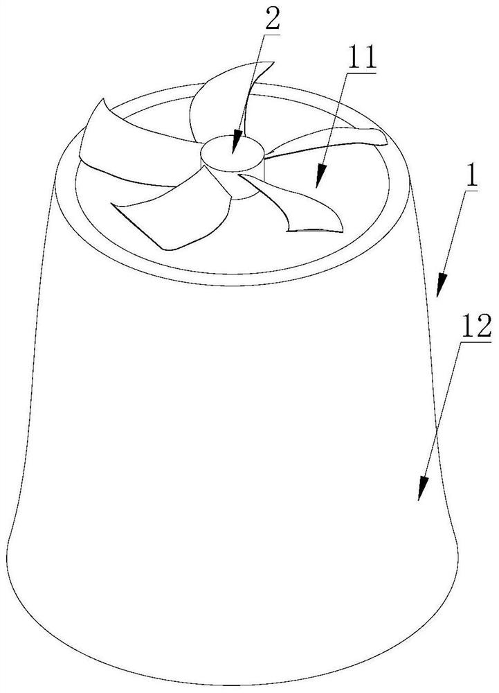
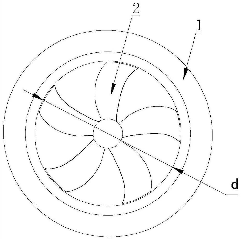
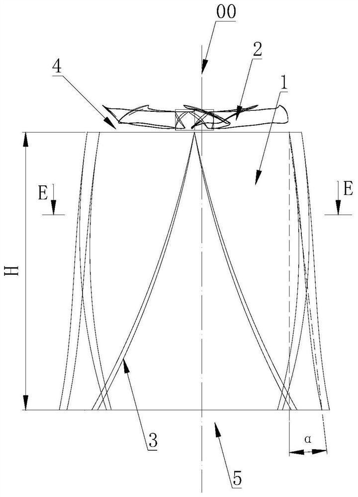
[0025] refer to Figure 1-4 , this embodiment discloses a twisted diffuser cylinder, which includes a cylinder body 1, the cylinder body 1 is provided with through ventilation holes along the axis 00 direction, the cylinder body 1 is set with equal wall thickness, and the two ends of the cylinder body 1 along the axis 00 direction are respectively It is the air inlet end 4 and the air outlet end 5. The side of the cylinder body 1 facing the axis 00 is the inner wall surface 11, and the side of the cylinder body 1 away from the axis 00 is the outer wall surface 12. The inner wall surface 11 and the outer wall surface 12 are arranged opposite to each other along the axis 00 From the air inlet end 4 to the air outlet end 5, the inner wall surface 11 gradually increases in cross-sectional area perpendicular to the axis 00;

[0026] The cylinder 1 is twisted along the coaxial helix 3, and is arranged along the axis 00 from the air inlet end 4 to the air outlet end 5. The cylinder 1...

Embodiment 2

[0038] refer to Figure 1-4 , the current collector is hidden in the figure, and this embodiment also discloses an axial flow fan, including a wind wheel 2 and a current collector, and the current collector is coaxially sleeved outside the wind wheel 2;

[0039] It also includes the above-mentioned twisted diffusion cylinder, the cylinder body 1 is coaxially arranged with the current collector, and the air inlet end 4 of the cylinder body 1 is connected to the air outlet of the current collector. The diameter of 4 is equal to the inner diameter of the current collector, and the helical direction of the helix 3 is opposite to that of the wind wheel 2 when it works.

[0040] The axial flow fan adopts a twisted diffuser cylinder. Since the cylinder 1 is twisted along the coaxial helix 3, and the rotation direction of the wind wheel 2 is opposite to that of the helix 3, when the airflow flows from the air outlet of the collector to the cylinder 1, the air flow generates a reverse...


PUM


Abstract

The invention discloses a twisted diffusion cylinder and an axial-flow fan applying the same. The twisted diffusion cylinder comprises a cylinder body, wherein through ventilation holes are formed in the cylinder body in the axis direction, the two ends, in the axis direction, of the cylinder body are an air inlet end and an air outlet end, and from the air inlet end to the air outlet end in the axis direction, the sectional area of the inner wall surface of the cylinder body is gradually increased in a manner of being vertical to the axis, and the cylinder body is arranged in a mode of being twisted along a coaxial spiral line. The axial-flow fan comprises a wind wheel and the cylinder body, wherein the spiral direction of the spiral line is opposite to the rotating direction of the wind wheel. The twisted diffusion cylinder and the axial-flow fan applying the same have the following beneficial effects: on the premise of not changing the original size and installation matching sizes, reverse secondary flow is generated when airflow passes through the cylinder body to weaken eddy and disturb a boundary layer on the inner wall surface, the rectification effect is enhanced, tangential airflow flowing is reduced, the flowing speed of the axial airflow is increased, the effects of pressurization, efficiency increasing, noise reduction and resistance reduction are further achieved on the basis of an original diffusion cylinder, and through experimental calculation, the efficiency is increased by 2% or above, and the noise is reduced by 2 dB (A) or above.

Description

technical field [0001] The invention relates to the technical field of ventilation, in particular to a twisted diffuser cylinder and an axial flow fan using the diffuser cylinder. Background technique [0002] At present, the market pays more and more attention to the performance of energy efficiency and noise in the application of axial flow fans, and puts forward higher requirements for the performance of fans. Generally, axial flow fans include wind wheels, collectors and diffusers, collectors Coaxially sleeved outside the wind wheel, the air inlet end of the diffuser is connected to the air outlet of the collector, and the diffuser is coaxially arranged with the collector. As an important part of the axial flow fan, the diffuser can improve The efficiency, noise and other performances of the fan, the airflow out of the impeller advances in a spiral manner according to the direction of rotation of the impeller, and the function of the diffuser is to use its airflow cross-...

Claims


Application Information

Patent Timeline
IPC IPC(8): F04D29/54F04D29/66F04D29/68
CPCF04D29/547F04D29/667F04D29/663F04D29/681
Inventor 郭小勇陈宗华
Owner FANS TECH ELECTRIC CO LTD
Learn More