A wind turbine blade clearance control method based on load detection

A wind turbine and control method technology, which is applied in the directions of engine control, engine control parameters, wind turbine control, etc., can solve the problems of the adverse effect of the power generation income level of the wind turbine, the reduction of the power generation performance of the wind turbine, and the inability to accurately identify the wind rotor, etc. Achieve the effect of avoiding power generation loss, reducing application restrictions, and improving safety

Active Publication Date: 2022-03-01
CRRC WIND POWER(SHANDONG) CO LTD
View PDF19 Cites 0 Cited by
  • Summary
  • Abstract
  • Description
  • Claims
  • Application Information

AI Technical Summary

Problems solved by technology

[0005] The inventor found that the control method of the wind turbine control system for the blade clearance is to increase the pitch angle of the blades, but because it cannot accurately identify the negative unbalanced load on the wind rotor and the occurrence of negative wind shear operating conditions, it requires The method of increasing blade pitch angle is adopted for all working conditions to achieve the purpose of increasing blade clearance
Increasing the pitch angle under all working conditions will inevitably lead to a decrease in the power generation performance of the wind turbine, which will have an adverse impact on the level of power generation revenue of the wind turbine. For the wind rotor to bear negative unbalanced loads, and with the specific operation of negative wind shear Due to the characteristics of working conditions, there is currently no targeted blade clearance control method that can avoid the loss of power generation caused by existing control methods

Method used


Image

  • A wind turbine blade clearance control method based on load detection
  • A wind turbine blade clearance control method based on load detection
  • A wind turbine blade clearance control method based on load detection

Examples


Embodiment 1

[0036] In a typical implementation of the present disclosure, such as Figure 1-Figure 4 As shown, a wind turbine blade clearance control method based on load detection is proposed.

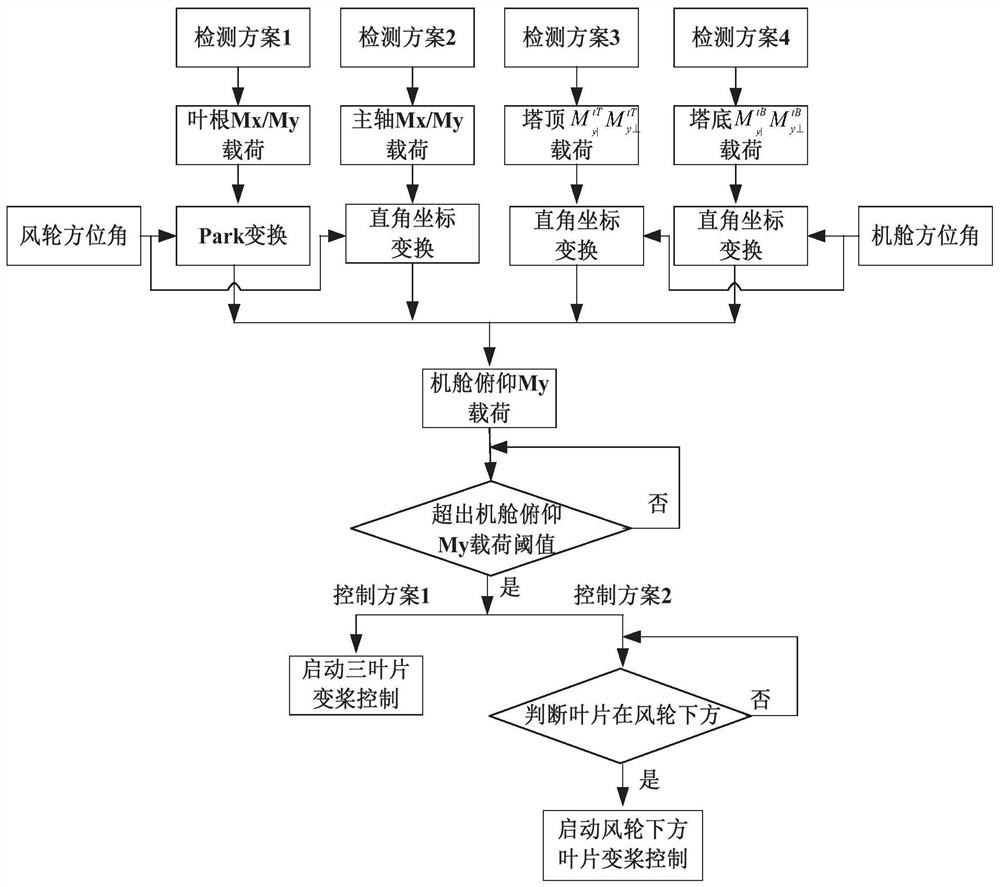
[0037] Taking the three-blade wind turbine as an example, the following steps are included:

[0038] Select three load detection points of the blade root, the main shaft, the vertical direction of the top of the tower, and the vertical direction of the bottom of the tower to establish a load detection method for key parts;

[0039] Use sensing equipment to detect the azimuth angle of the wind wheel and nacelle yaw;

[0040] Transform the loads of key parts into the loads in the pitch direction of the nacelle in the stationary hub coordinate system;

[0041] Through the wind turbine simulation software and according to the design specifications, the negative load threshold is obtained, and the pitch protection angle is determined;

[0042] Adopt three-blade unified pitch or downwind blade indep...

Embodiment 2

[0073] In another typical implementation of the present disclosure, such as Figure 1-Figure 4 As shown, a wind turbine blade clearance control method based on load detection is proposed.

[0074] A 3.0MW wind turbine is especially suitable for high-power wind turbines with long blades. figure 1 As shown, the steps include:

[0075] (a) Select three load detection points on the blade root, the main shaft, the vertical direction of the top of the tower, and the vertical direction of the bottom of the tower. The detection methods include but are not limited to optical fiber gratings and resistive strain gauges.

[0076] (b) Use sensing devices such as encoders and proximity switches to detect the azimuth angle of the wind rotor and nacelle yaw.

[0077] (c) For the detection scheme of the My load on the root of the three blades, the My load on the blade root of the three blades is transformed into the My load in the pitch direction of the nacelle in the static hub coordinate s...


PUM


Abstract

The disclosure provides a load detection-based blade clearance control method for wind turbines, which relates to the field of wind turbine regulation and control, selects detection points for key parts of the wind turbine structure, and performs load detection on key parts; , transform the detected load on key parts into the load in the pitching direction of the nacelle in the stationary hub coordinate system; through the wind turbine simulation software and according to the design specifications, obtain the negative threshold of the nacelle pitching load, and determine the pitch protection angle; use the wind turbine blade Root, main shaft, tower top, tower bottom and other key parts of the load, identify the negative pitching load on the wind rotor, and with the characteristics of specific operating conditions of negative wind shear, combined with the targeted pitch angle control method, to achieve Purpose of increasing blade clearance.

Description

technical field [0001] The present disclosure relates to the field of regulation and control of wind turbines, and in particular to a method for controlling blade clearance of wind turbines based on load detection. Background technique [0002] The statements in this section merely provide background information related to the present disclosure and may not necessarily constitute prior art. [0003] With the development of the wind power industry, in order to increase the annual power generation and economic benefits of wind turbines, wind turbines are developing in the direction of longer blades and higher towers. At the same time, in order to meet the grid parity of wind power, new requirements are put forward on the unit kilowatt cost of wind turbines. The cost of blades accounts for about 30% of the cost of the whole machine. In the design process of high-power long-blade wind turbines, how to effectively control the design weight of blades is a key An important factor ...

Claims


Application Information

Patent Timeline
Patent Type & Authority Patents(China)
IPC IPC(8): F03D7/04F03D17/00
CPCF03D7/0224F03D7/024F03D7/0264F03D17/00F05B2270/329F05B2270/331F05B2270/33Y02E10/72
Inventor 关中杰田家彬李钢强刘南南刘翠翠牛成
Owner CRRC WIND POWER(SHANDONG) CO LTD
Why Eureka
Try Eureka