Engine motion structure with variable compression ratio

A technology of motion structure and compression ratio, applied in engine control, machine/engine, mechanical equipment, etc., can solve problems such as ablation, gear device wear, worm device deformation, etc., to achieve simple motion structure, reduce energy loss, and reliability high effect

Active Publication Date: 2021-04-06
DONGFENG MOTOR CORP HUBEI
View PDF12 Cites 0 Cited by
  • Summary
  • Abstract
  • Description
  • Claims
  • Application Information

AI Technical Summary

Problems solved by technology

The disadvantage of this patent is: the cylinder head is a part that withstands high temperature and high pressure, and the worm device may be deformed, ablated, stuck, etc. due to high temperature and high pressure, and its reliability is not high
The disadvantage of this patent is: frequent changes in the engine compression ratio will cause wear of the gear device, and the reliability is not high
The disadvantages of this patent are: the processing of the eccentric camshaft is complicated, the cost is high, and the energy consumption required for the relative movement between the crankcase and the cylinder block is high

Method used


Image

  • Engine motion structure with variable compression ratio
  • Engine motion structure with variable compression ratio
  • Engine motion structure with variable compression ratio

Examples


Embodiment Construction

[0025] The present invention will be further described in detail below in conjunction with the accompanying drawings and specific embodiments.

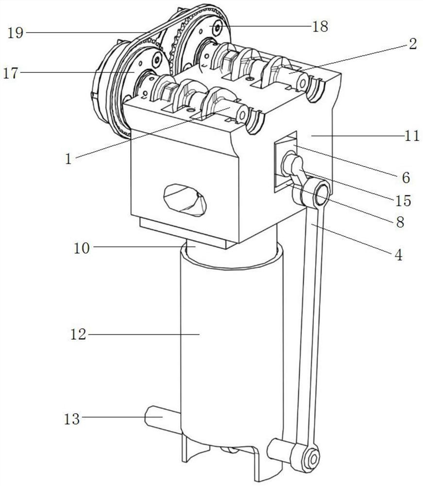
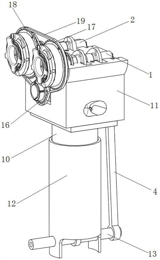
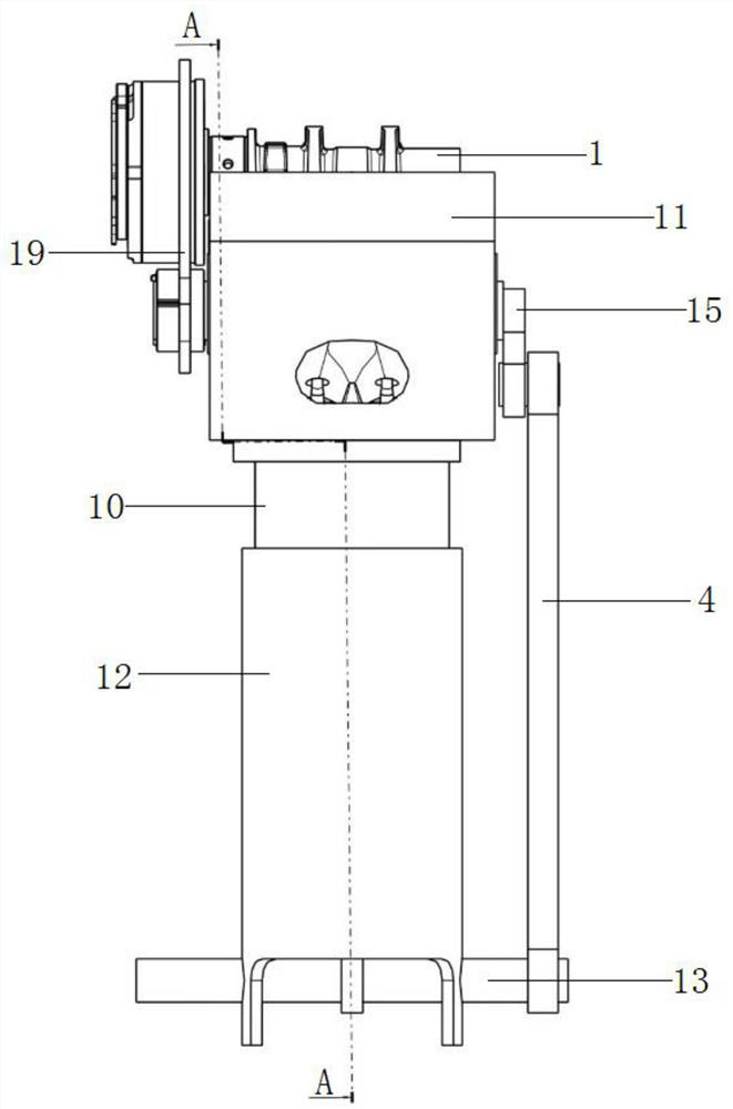
[0026] Such as figure 1 -The variable compression ratio engine kinematic structure shown in 5, comprises cylinder, and cylinder comprises cylinder housing 10 and the cylinder head 11 that is fixed on cylinder housing 10 tops, intake camshaft 1 and exhaust camshaft 2 are arranged in parallel on the top of the cylinder head 11, and the piston 3 is arranged in the cylinder housing 10.

[0027] The piston 3 is connected with a cross-bar sleeve mechanism that can move up and down with it: it includes a guide sleeve 12 that is coaxially sleeved on the cylinder housing 10, moves up and down along the cylinder housing 10 axis, and a diameter along the guide sleeve 12. To the cross bar 13 fixed on the bottom of the guide sleeve 12, a piston rod 14 is connected between the piston 3 and the cross bar 13, and the top and bottom ends of the pisto...


PUM


Abstract

The invention discloses an engine motion structure with variable-compression-ratio. The engine motion structure comprises an air cylinder, an air inlet cam shaft and an air outlet cam shaft, the air inlet cam shaft and the air outlet cam shaft are arranged on the air cylinder in parallel, and a piston capable of moving up and down is arranged in the air cylinder and fixedly connected with a transverse rod sleeve mechanism capable of moving up and down along with the piston, a connecting rod is connected with the transverse rod sleeve mechanism in a hinged mode, a motion conversion mechanism capable of converting linear motion into rotary motion is hinged to the top of the connecting rod, a gear shaft parallel to the air inlet cam shaft and the air outlet cam shaft is fixed to the power output end of the motion conversion mechanism, and the gear shaft is rotatably connected with the air inlet cam shaft and the air outlet cam shaft through a gear transmission mechanism. The gear shaft is arranged in a trapezoidal sliding block with the top face being an inclined face, a wedge-shaped block matched with the trapezoidal sliding block is arranged in the air cylinder, the bottom face of the wedge-shaped block is an inclined face, and a sliding block guide groove allowing the trapezoidal sliding block to move up and down and a wedge-shaped block guide groove allowing the wedge-shaped block to move left and right are formed in the air cylinder. The engine compression ratio is adjustable, the motion structure is simple, stable and reliable, and the energy consumption is low.

Description

technical field [0001] The invention relates to the technical field of engines, in particular to an engine motion structure with variable compression ratio. Background technique [0002] The engine compression ratio is the ratio of the maximum stroke volume of the piston to the minimum stroke volume, and its calculation formula is: compression ratio = V1 / V2. As far as a certain cylinder of the engine is concerned, when the stroke of the piston reaches the lowest point, the position of the piston at this time is called the bottom dead center, and the volume in the combustion chamber of the cylinder is the maximum stroke volume V1. When the piston moves in the opposite direction, it reaches the highest point position , the position of the piston at this time is called the top dead center, the volume of the combustion chamber is the smallest in the entire piston stroke, and the volume is V2. The compression ratio of a general engine cannot be changed, because the volume of the...

Claims


Application Information

Patent Timeline
Patent Type & Authority Applications(China)
IPC IPC(8): F02D15/02F02B75/04F02B75/32
CPCF02D15/02F02B75/04F02B75/32
Inventor 章帅韬
Owner DONGFENG MOTOR CORP HUBEI
Why Eureka
Try Eureka