
High-rigidity and high-damping satellite platform configuration

A satellite platform, high damping technology, applied in artificial satellites, space navigation equipment, space navigation equipment, etc., can solve the problem of large and complex structures that are not suitable for dense modalities, do not meet the requirements of lightweight development of satellites, increase additional mass, etc. problems, to achieve the effect of large structural space utilization, increased structural rigidity, and reduced overall center of mass

Inactive Publication Date: 2021-04-06
CHANGGUANG SATELLITE TECH CO LTD
View PDF4 Cites 2 Cited by
  • Summary
  • Abstract
  • Description
  • Claims
  • Application Information

AI Technical Summary

Problems solved by technology

[0004] 1) The decoupling method needs to be adjusted between different structural frequencies, which is complicated and needs to be increased at the cost of additional mass, and is not suitable for large and complex structures with dense modes;
[0005] 2) Vibration isolation technology mainly uses vibration isolators to isolate sensitive equipment that needs vibration reduction. Its disadvantage is that it is easy to introduce a resonance amplification peak in the low-frequency vibration area and the structural stability is poor;
[0006] 3) The stiffening method is to increase the natural frequency of the structural parts by increasing the structural stiffness to release the coupling effect with the excitation. It often needs to increase the additional mass as a cost, which does not meet the development requirements of satellite light weight

Method used


Image

  • High-rigidity and high-damping satellite platform configuration
  • High-rigidity and high-damping satellite platform configuration
  • High-rigidity and high-damping satellite platform configuration

Examples


Embodiment Construction

[0045] In order to enable those skilled in the art to better understand the technical solutions of the present invention, the present invention will be further described in detail below in conjunction with the accompanying drawings.

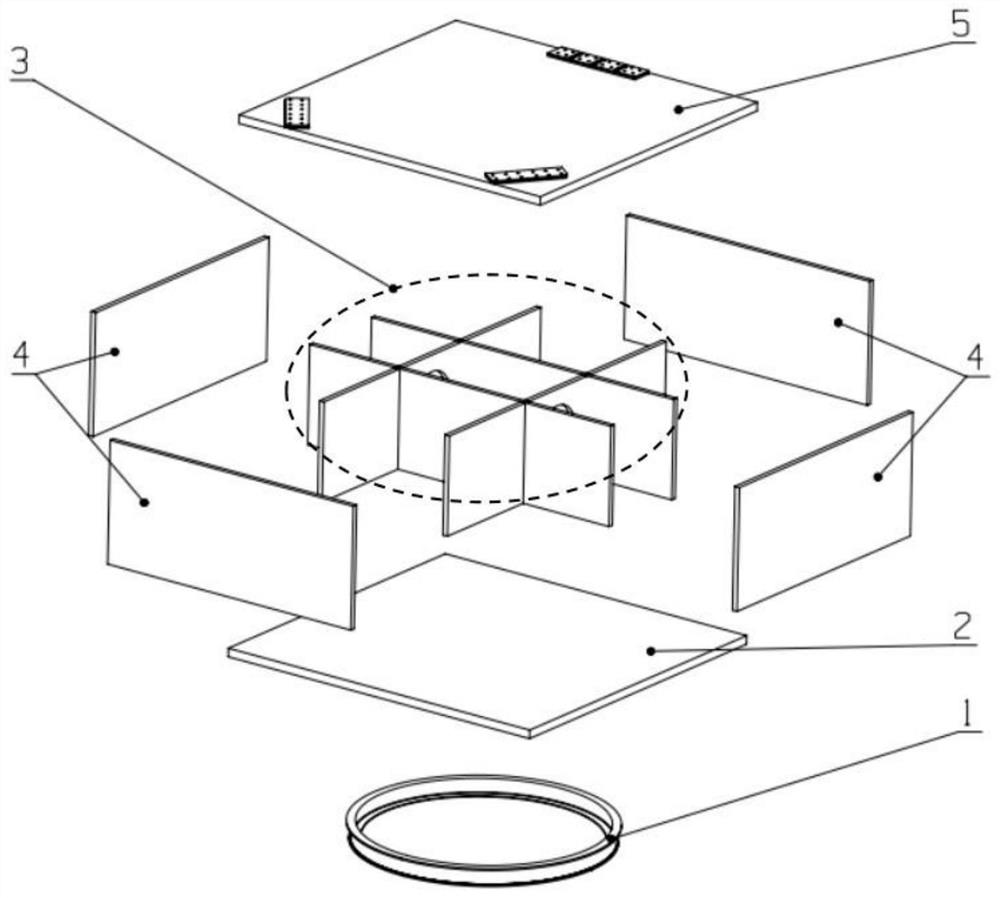
[0046] see figure 1 shown;

[0047] Star Arrow docking ring 1, which is used to dock with the rocket adapter;

[0048] The mounting plate, one side of which is fixedly connected to the star-arrow docking ring 1, and the other side is fixedly connected with an optical load plate 5, and the optical load plate 5 carries an optical load;

[0049] A damping layer 6 is laid on the outer surface of the optical load plate 5 and the outer wall of the star-arrow docking ring 1;

[0050] A constraining layer 7 is laid on the outer surface of the damping layer 6 .

[0051] Preferably, the damping layer 6 is made of butyl rubber or silicon rubber;

[0052] The constrained layer 7 is made of aluminum alloy, magnesium alloy or honeycomb plate.

[0053] Spe...


PUM


Abstract

The invention discloses a high-rigidity and high-damping satellite platform configuration, which belongs to the field of overall design of spacecrafts and comprises a satellite-rocket butt joint ring used for being in butt joint with a rocket adapter; a mounting plate, wherein one side of the mounting plate is fixedly connected with the satellite-rocket butt joint ring, the other side of the mounting plate is fixedly connected with an optical load plate, and the optical load plate bears an optical load; damping layers which are laid on the outer surface of the optical loading plate and the outer wall of the satellite-rocket butt joint ring; a restraint layer which is laid on the outer surface of the damping layer; the mounting plate comprises a butt joint plate, a partition plate, an outer plate and an optical load plate; the partition plate is of a #-shaped structure, the outer plate is arranged on the periphery of the partition plate, the butt joint plate, the partition plate, the outer plate and the optical load plate are all aluminum honeycomb sandwich plates, and embedded parts are embedded in the single-machine equipment installation position and the rigidity reinforcing position of the aluminum honeycomb sandwich plates. The high-rigidity and high-damping satellite platform configuration has advantages of convenient single equipment configuration and installation, and high space utilization ratio. On the premise that the system is high in rigidity and small in additional mass, structural damping is effectively increased so as to attenuate vibration response of all components of the system.

Description

technical field [0001] The invention relates to the technical field of overall design of spacecraft, in particular to a high-rigidity and high-damping satellite platform configuration. Background technique [0002] Satellites are subject to mechanical environments such as vibration, shock, noise, acceleration, and microgravity during the stages of manufacturing assembly, ground transportation, reflection into orbit, on-orbit operation, and active return. This mechanical environment not only reduces the precision of electronic instruments and equipment on the satellite Accuracy and reliability, but also greatly reduce the fatigue life and service time of structural parts; [0003] At present, the traditional vibration reduction methods mainly include decoupling, vibration isolation and structural rigidity, etc., all of which have defects; [0004] 1) The decoupling method needs to be adjusted between different structural frequencies, which is complicated and needs to be incr...

Claims


Application Information

Patent Timeline
IPC IPC(8): B64G1/10B64G1/22B64G1/64
CPCB64G1/10B64G1/22B64G1/646
Inventor 肖钧凯张雷郑晓峰谷松陈善搏高飞
Owner CHANGGUANG SATELLITE TECH CO LTD
Learn More