Eureka AIR delivers breakthrough ideas for toughest innovation challenges, trusted by R&D personnel around the world.

Guide vane ring feeding device based on visual positioning and using method thereof

A technology of visual positioning and visual device is applied in the field of guide vane mouth ring feeding device based on visual positioning, which can solve the problems of high quality and high efficiency, which are difficult to guarantee, and achieve the effects of simple structure, convenient maintenance and increased reliability.

Inactive Publication Date: 2021-04-06
WUHU HIT ROBOT TECH RES INST
View PDF13 Cites 1 Cited by
  • Summary
  • Abstract
  • Description
  • Claims
  • Application Information

AI Technical Summary

Problems solved by technology

[0005] In view of the deficiencies in the prior art, the purpose of the present invention is to provide a guide vane mouth ring feeding device based on visual positioning. The existing problems of high quality and high efficiency are difficult to guarantee, and the automatic feeding of vibrating discs has the problem of material stacking, material blocking and other material loading failures; the invention also provides a method for using a guide vane mouth ring feeding device based on visual positioning

Method used


Image

  • Guide vane ring feeding device based on visual positioning and using method thereof
  • Guide vane ring feeding device based on visual positioning and using method thereof
  • Guide vane ring feeding device based on visual positioning and using method thereof

Examples


Embodiment Construction

[0027] In the present invention, it should be understood that the terms "length"; "width"; "upper"; "lower"; "front"; "back"; "left"; "right"; "vertical"; "; "Top"; "Bottom" "Inner"; "Outer"; "Clockwise"; "Counterclockwise"; "Axial"; "Plane Direction"; The orientations or positional relationships shown in the drawings are only for the convenience of describing the present invention and simplifying the description, rather than indicating or implying that the referred device or element must have a specific orientation; it is constructed and operated in a specific orientation, so it cannot be understood as Limitations on the Invention.

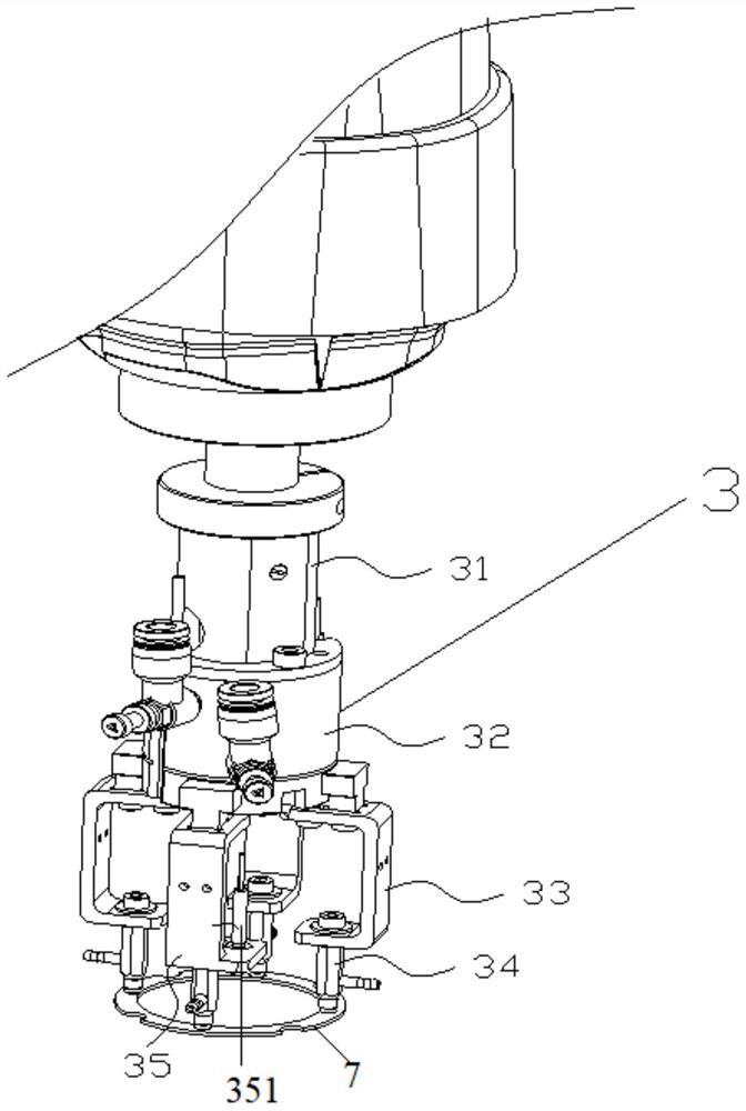
[0028] Such as Figure 1 to Figure 3 As shown, a guide vane mouth ring feeding device based on vision positioning includes a base 1, a SCARA robot 2, an end effector 3 for picking and placing the guide vane mouth ring 7, an incoming material slide 4 and a The vision device 6 for performing visual inspection on the blade mouth ring 7 and positio...


PUM


Abstract

The invention discloses a guide vane ring feeding device based on visual positioning. The guide vane ring feeding device comprises a base, an SCARA robot, an end effector used for taking and placing guide vane rings, a feeding slideway and a visual device, wherein the base is mounted on a workbench; the SCARA robot is fixedly mounted on the base; the end effector is connected to the tail end of the SCARA robot; the feeding slideway is connected to the visual device and located on the lower right portion of the end effector; the visual device is fixedly mounted on the workbench and located on the lower left portion of the feeding slideway; and the visual device conducts visual inspection and positioning on the guide vane rings coming from the feeding slideway in the previous procedure, and preparation is made for feeding of the robot in the next step. The guide vane ring feeding device further comprises a removing device used for removing the guide vane rings which are unqualified after visual inspection of the visual device; and the removing device is fixedly mounted on the upper rear portion of the visual device and located on the left side of the feeding slideway and used for removing the guide vane rings which are unqualified after visual inspection of the visual device.

Description

technical field [0001] The invention belongs to the technical field of water pump guide vane manufacturing, and in particular relates to a guide vane opening ring feeding device based on visual positioning and a use method thereof. Background technique [0002] A water pump is a machine that transports liquid or pressurizes a liquid. According to different working principles, it can be divided into volumetric water pump, vane pump and other types. The guide vane is the energy transfer device of the centrifugal pump. Its function is to collect the liquid thrown out by the impeller, reduce the flow rate of the liquid, and convert part of the velocity energy head into the pressure energy head, and then evenly introduce it into the next stage or pass through it. Diffusion tube discharge. The guide vane ring is an important part of the guide vane, which can effectively prevent the wear of the impeller during operation. [0003] The traditional manufacturing method of the guide ...

Claims


Application Information

Patent Timeline
Patent Type & Authority Applications(China)
IPC IPC(8): B29C65/78B07C5/02B07C5/342B07C5/36
CPCB29C65/78B07C5/02B07C5/3422B07C5/362B07C2501/0063
Inventor 胡松李龙徐昌军于福才陶贤水
Owner WUHU HIT ROBOT TECH RES INST
Why Eureka
Eureka Blog
Learn More