
Flame cutting equipment for steel plate profile machining

A flame cutting and profile technology, applied in the direction of metal processing equipment, gas flame welding equipment, welding equipment, etc., can solve the problem of poor adjustability and adaptability of cutting equipment, low efficiency of processing and cutting, and inability to adjust the diameter of round parts. Size and other issues to achieve the effect of improving adjustability and adaptability and improving work efficiency

Inactive Publication Date: 2021-04-06
诸暨企周贸易有限公司
View PDF8 Cites 2 Cited by
  • Summary
  • Abstract
  • Description
  • Claims
  • Application Information

AI Technical Summary

Problems solved by technology

[0004] The object of the present invention is to provide a kind of flame cutting equipment for steel plate profile processing, by setting the base assembly, front frame assembly, rear frame assembly, guide assembly, mounting assembly and cutting assembly, to solve the traditional steel plate in the background technology During the use of flame cutting equipment for profile processing, due to the poor adjustability and adaptability of the cutting equipment, the diameter of the round block parts cannot be adjusted, and it is difficult to meet the processing and production requirements for round block parts with different diameters and specifications. , the problem of low work efficiency in processing and cutting

Method used


Image

  • Flame cutting equipment for steel plate profile machining
  • Flame cutting equipment for steel plate profile machining
  • Flame cutting equipment for steel plate profile machining

Examples


Embodiment Construction

[0027] The present invention will be further described below in conjunction with the examples.

[0028] The following examples are used to illustrate the present invention, but cannot be used to limit the protection scope of the present invention. The conditions in the embodiment can be further adjusted according to the specific conditions, and the simple improvement of the method of the present invention under the premise of the concept of the present invention belongs to the protection scope of the present invention.

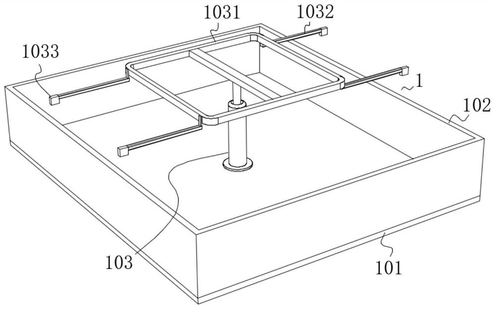
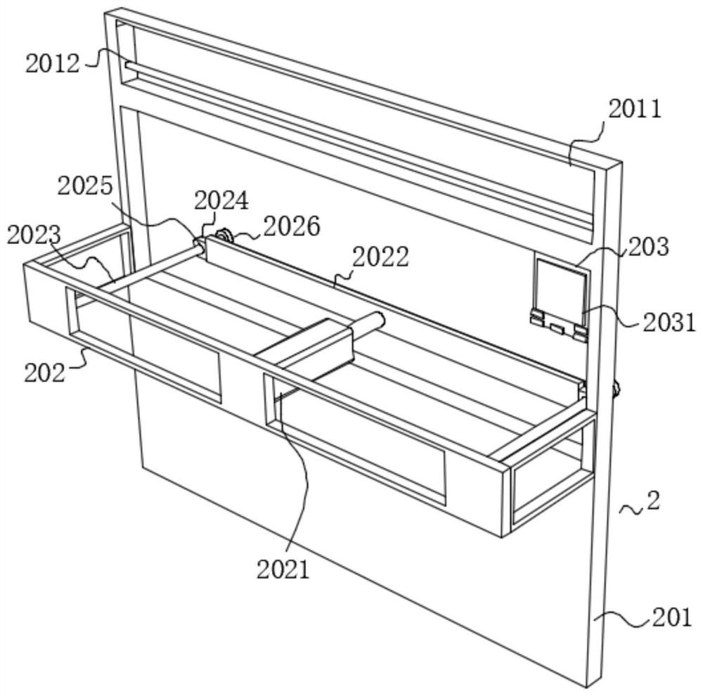
[0029] see Figure 1-7 , the present invention provides a kind of flame cutting equipment for steel profile processing, comprising a base assembly 1, one end of the base assembly 1 is provided with a front frame assembly 2, the other end of the base assembly 1 is provided with a rear frame assembly 3, the front frame assembly 2 and the rear A guide assembly 4 is provided between the rack assemblies 3, a rack assembly 5 is provided on the bottom side of the gu...


PUM


Abstract

The invention discloses flame cutting equipment for steel plate profile machining, and belongs to the technical field of steel plate profile machining. The flame cutting equipment comprises a base assembly, a front frame assembly is arranged at one end of the base assembly, a rear frame assembly is arranged at the other end of the base assembly, a guide assembly is arranged between the front frame assembly and the rear frame assembly, a mounting assembly is arranged on the bottom side of the guide assembly, a cutting assembly is arranged on the bottom side of the mounting assembly, and the base assembly comprises a fixed base. A material receiving groove is fixedly formed in the upper end of the fixed base, an electric push rod is fixedly installed at the upper end of the inner side of the material receiving groove, a material carrying bracket is fixedly installed at the telescopic end of the electric push rod, the front frame assembly comprises an assembly front frame, and a guide through opening is formed in the surface of the assembly front frame. The machining and cutting work efficiency can be improved, the machining and manufacturing diameter size of round block parts can be adjusted, the machining and manufacturing use requirements suitable for the round block parts of different diameter specifications can be met conveniently, and the adjustability and adaptability of cutting equipment are improved.

Description

technical field [0001] The invention belongs to the technical field of steel plate profile processing, and in particular relates to a flame cutting device for steel plate profile processing. Background technique [0002] Steel products are widely used and have various varieties. According to the different cross-sectional shapes, steel products are generally divided into four categories: profiles, plates, pipes and metal products. Steel is a material of a certain shape, size and performance made of steel ingots, billets or steel through pressure processing. Most steel processing is through pressure processing, which causes plastic deformation of the processed steel (billet, ingot, etc.). According to the different processing temperature of steel, it can be divided into cold processing and hot processing. Carbon steel is also called carbon steel, which is an iron-carbon alloy with a carbon content of less than 2%. In addition to carbon, carbon steel generally contains a smal...

Claims


Application Information

Patent Timeline
Patent Type & Authority Applications(China)
IPC IPC(8): B23K7/00B23K7/10
CPCB23K7/00B23K7/10
Inventor 周铁
Owner 诸暨企周贸易有限公司
Learn More