Building waste treatment equipment
A technology for processing equipment and construction waste, applied in the field of construction, can solve the problems of lack of precise crushing function and inconvenient use
- Summary
- Abstract
- Description
- Claims
- Application Information
AI Technical Summary
Problems solved by technology
Method used
Image

Examples
specific Embodiment approach 1
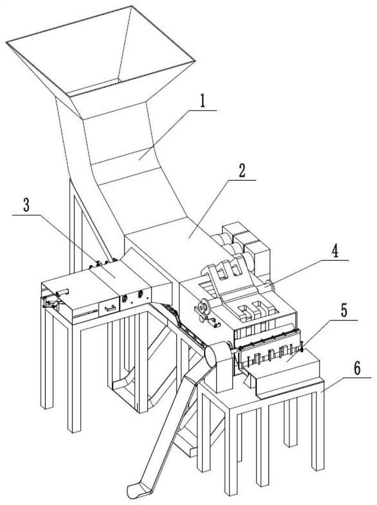
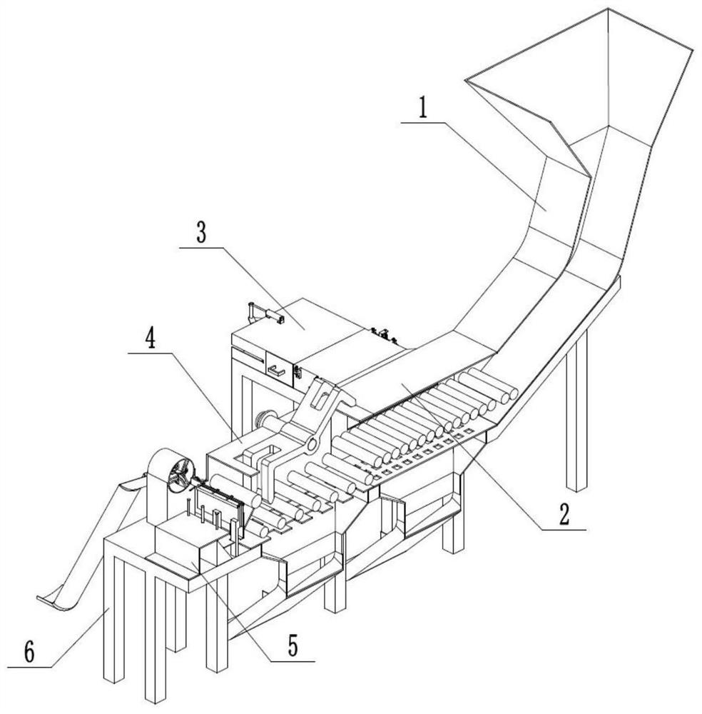
[0047] Combine below Figure 1-28 Describe this embodiment, a construction waste treatment equipment, including a feeding device 1, a plastic separating device 2, a plastic processing device 3, a rock breaking device 4, a steel bar processing device 5, and a base 6, and the feeding device 1 is separated from the plastic The device 2 is connected, the plastic processing device 3 and the stone-breaking device 4 are connected with the plastic separation device 2, the stone-breaking device 4 is connected with the steel bar processing device 5, the feeding device 1, the plastic separation device 2, the plastic processing device 3, The rock breaking device 4 and the reinforcing bar processing device 5 are all connected with the base 6 .
specific Embodiment approach 2
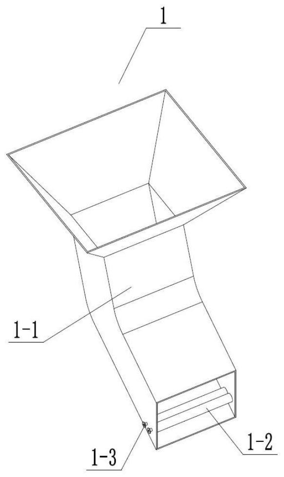
[0049] Combine below Figure 1-28 Describe this embodiment, this embodiment will further explain Embodiment 1, the feed device 1 includes a feed port 1-1, a conveying roller A1-2, a gear A1-3, the two ends of the conveying roller A1-2 are connected to the feeding The inner wall of the port 1-1 is fixedly connected, the rear end of the gear A1-3 is fixedly connected with the left end of the feed port 1-1, and the inner hole of the gear A1-3 is rotationally connected with the front end of the conveying roller A1-2;
[0050] After the garbage is injected into the feed port 1-1, it falls on the conveying roller A1-2, and the conveying roller A1-2 rotates under the drive of the gear A1-3, and the garbage is sent to the conveying roller B2-2.
specific Embodiment approach 3
[0052] Combine below Figure 1-28 Describe this embodiment, this embodiment will further explain Embodiment 1, the plastic separation device 2 includes a plastic material blocking frame 2-1, a conveying roller B2-2, a fine screen 2-3, a fan blade 2-4, and a blower 2-5, motor 2-6, gear B2-7, blanking port A2-8, double gear A2-9, gear C2-10, chain A2-11, bevel gear A2-12, chain B2-13, double gear B2-14, double gear C2-15, the left end of the plastic material retaining frame 2-1 is welded to the front end of the feed inlet 1-1, and the two ends of the fine screen 2-3 are welded to the inner side of the plastic material retaining frame 2-1. The upper end of the feed port A2-8 is welded to the lower end of the fine screen 2-3, the conveying roller B2-2 is rotationally connected to the plastic retaining frame 2-1, the inner hole of the double gear A2-9 is rotationally connected to the front end of the conveying roller B2-2, The inner hole of the gear C2-10 is rotationally connected...
PUM
 Abstract
Description
Claims
Application Information
 - R&D
- Intellectual Property
- Life Sciences
- Materials
- Tech Scout
- Unparalleled Data Quality
- Higher Quality Content
- 60% Fewer Hallucinations
Browse by: Latest US Patents, China's latest patents, Technical Efficacy Thesaurus, Application Domain, Technology Topic, Popular Technical Reports.
© 2025 PatSnap. All rights reserved.Legal|Privacy policy|Modern Slavery Act Transparency Statement|Sitemap|About US| Contact US: help@patsnap.com