
A current control method for a hydrogen fuel cell dc-dc converter device

A DC-DC, fuel cell technology, applied in the output power conversion device, the conversion of DC power input to DC power output, and the adjustment of electrical variables, etc., can solve the problems affecting the economy and practicability of new energy vehicles Early derating, large branch temperature difference, etc., to achieve the effect of improving economy and practicability, realizing intelligent control, and improving load capacity

Active Publication Date: 2021-12-07
SHENZHEN LANDE AUTOMOBILE POWER SUPPLY TECHCO
View PDF6 Cites 0 Cited by
  • Summary
  • Abstract
  • Description
  • Claims
  • Application Information

AI Technical Summary

Problems solved by technology

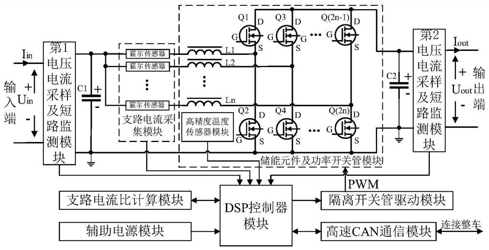
In practical applications, it is difficult to achieve complete consistency between the power devices of each branch in a multi-phase interleaved parallel circuit, and it is also difficult for the heat dissipation system to evenly dissipate heat from each branch.
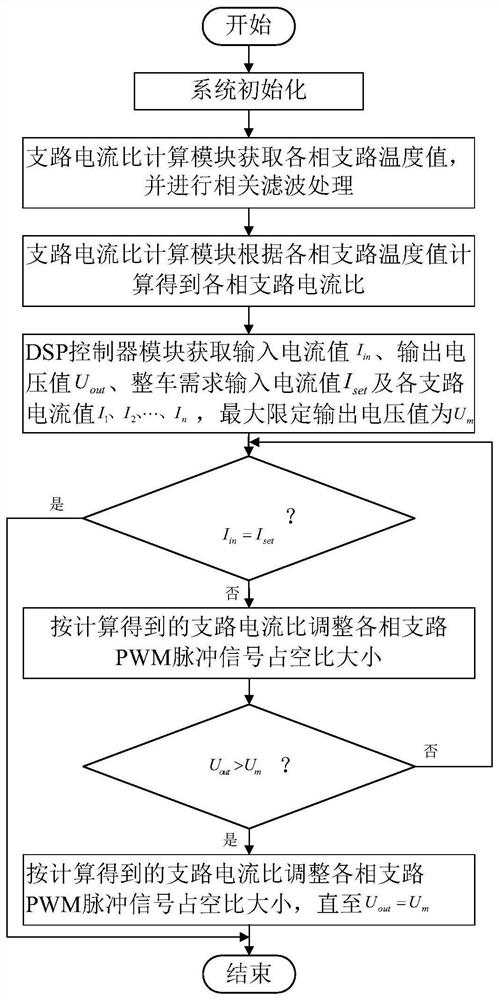
In view of the above problems, traditional hydrogen fuel cell DC-DC converters often use current sharing technology to achieve thermal balance of multi-phase interleaved parallel circuits as much as possible. There is a problem of large temperature difference in each branch, which leads to problems such as early derating of the converter, poor performance of over-temperature protection, and even low reliability problems such as equipment damage, which affects the performance of the hydrogen fuel cell DC-DC converter. Safety and stability further affect the economy and practicability of new energy vehicles

Method used


Image

  • A current control method for a hydrogen fuel cell dc-dc converter device
  • A current control method for a hydrogen fuel cell dc-dc converter device
  • A current control method for a hydrogen fuel cell dc-dc converter device

Examples


Embodiment Construction

[0025] The present invention will be further described in detail below in conjunction with the embodiments and the accompanying drawings, but the embodiments of the present invention are not limited thereto.

[0026] Unless otherwise defined, all technical and scientific terms used herein have the same meaning as commonly understood by one of ordinary skill in the technical field of the invention. The terminology used herein in the description of the present invention is only for the purpose of describing specific embodiments, and is not intended to limit the present invention. As used herein, the term "and / or" includes any and all combinations of one or more of the associated listed items.

[0027] For the existing hydrogen fuel cell DC-DC converter based on multi-phase interleaved parallel circuit, the temperature difference of each branch is relatively large when it operates in a relatively harsh environment for a long time, resulting in poor performance such as early derat...


PUM


Abstract

The invention relates to the technical field of DC-DC converters, in particular to a current control method for a hydrogen fuel cell DC-DC converter device. The branch current acquisition module is responsible for collecting the real-time current of each phase branch and transmitting it to the DSP controller module. The branch current acquisition module, the first voltage and current sampling and short-circuit monitoring module, and the second voltage and current sampling and short-circuit monitoring module are all electrically connected to the input end of the DSP controller module, and the output end of the DSP controller module is connected to the drive module of the isolation switch tube. The energy storage element and the input terminal of the power isolation switch tube module are electrically connected; the first voltage and current sampling and short-circuit monitoring module and the second current sampling and short-circuit monitoring module are respectively responsible for collecting the voltage and current of the input terminal and the voltage and current of the output terminal, and are responsible for real-time monitoring The input and output current can quickly respond to the situation of overcurrent or short circuit in the circuit, and quickly transmit the warning signal to the DSP controller module.

Description

technical field [0001] The invention relates to the technical field of DC-DC converters, in particular to a current control method for a hydrogen fuel cell DC-DC converter device. Background technique [0002] With the increasingly serious problems of environmental pollution and energy crisis, hydrogen fuel cell vehicles have gradually become a research hotspot in the field of new energy vehicles. Due to the slow dynamic response and soft characteristics of hydrogen fuel cells, and the large range of voltage changes, they cannot better meet the needs of the entire vehicle. Usually, a DC / DC converter is required to achieve the purpose of voltage decoupling and power control. [0003] Hydrogen fuel cell vehicles have extremely high requirements on parameters such as volume power density and conversion efficiency of hydrogen fuel cell DC-DC converters. In order to increase the volume power density, we often use multi-phase interleaved parallel technology to increase the rated ...

Claims


Application Information

Patent Timeline
Patent Type & Authority Patents(China)
IPC IPC(8): H02M3/158
CPCH02M3/1584
Inventor 石画张盛明
Owner SHENZHEN LANDE AUTOMOBILE POWER SUPPLY TECHCO
Learn More