
Refractive index model distortion correction method

A distortion correction and refractive index technology, applied in image enhancement, image analysis, instruments, etc., can solve problems such as large amount of calculation and no direct expression, and achieve the effect of small amount of calculation and simple software implementation.

Pending Publication Date: 2021-04-02
SHANGHAI AEROSPACE CONTROL TECH INST
View PDF3 Cites 0 Cited by
  • Summary
  • Abstract
  • Description
  • Claims
  • Application Information

AI Technical Summary

Problems solved by technology

However, the equation to solve the actual coordinates by the sun measured target is a transcendental equation, there is no direct expression, and it needs to be obtained through multiple iterative calculations
The advantage of this method is that only the relevant physical parameters of the refractive index model are required, and the mathematical meaning is clear; the disadvantage is that in a software operation cycle class, several iterations are required to obtain the corrected actual coordinates of the sun, and the amount of calculation is relatively large.
That is, for the correction of Newton's iterative calculation method, it is necessary to solve the equation through repeated iterative calculations within one computer operation cycle, which requires a large amount of calculation

Method used


Image

  • Refractive index model distortion correction method
  • Refractive index model distortion correction method
  • Refractive index model distortion correction method

Examples


Embodiment Construction

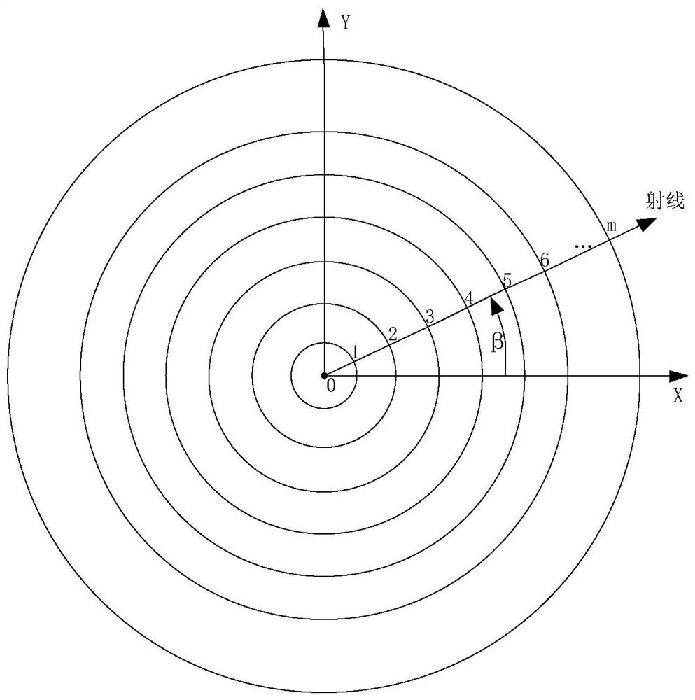
[0050] A method for correcting distortion of a refractive index model based on single-parameter fitting proposed by the present invention will be further described in detail below with reference to the accompanying drawings and specific embodiments. The advantages and features of the present invention will become clearer from the following description. It should be noted that the drawings are in a very simplified form and all use imprecise scales, which are only used to facilitate and clearly assist the purpose of illustrating the embodiments of the present invention. In order to make the objects, features and advantages of the present invention more comprehensible, please refer to the accompanying drawings. It should be noted that the structures, proportions, sizes, etc. shown in the drawings attached to this specification are only used to match the content disclosed in the specification, for those who are familiar with this technology to understand and read, and are not used...


PUM


Abstract

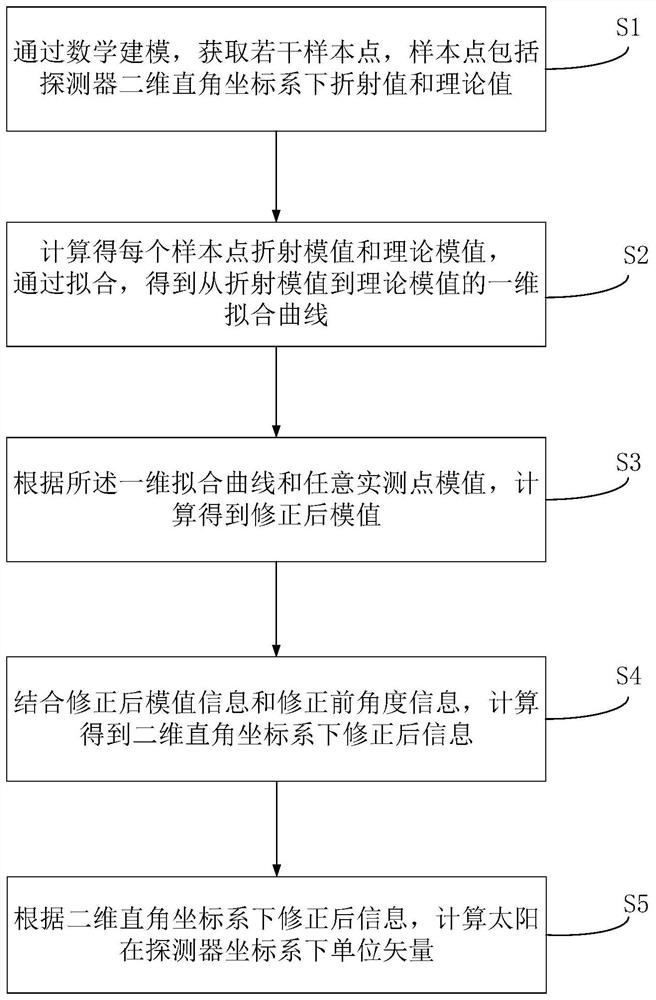
The invention discloses a refractive index model distortion correction method, which comprises the steps of obtaining a plurality of sample points through mathematical modeling, each sample point comprising a refraction value and a theoretical value of a solar facula centroid under a two-dimensional rectangular coordinate system of a detector; calculating to obtain a refraction module value and atheoretical module value of each sample point, and fitting the refraction module values and the theoretical module values of all the sample points to obtain a one-dimensional fitting curve from the refraction module values to the theoretical module values; calculating to obtain corrected module value information according to the one-dimensional fitting curve and the module value of any actual measurement point; calculating to obtain corrected solar facula centroid coordinate information under a two-dimensional rectangular coordinate system of the detector in combination with the corrected module value information and the uncorrected solar facula centroid coordinate information; and calculating to obtain a unit vector of the sun under the two-dimensional rectangular coordinate system of thedetector according to the corrected solar facula centroid coordinate information. The method has the advantages of being easy to implement and small in calculated amount.

Description

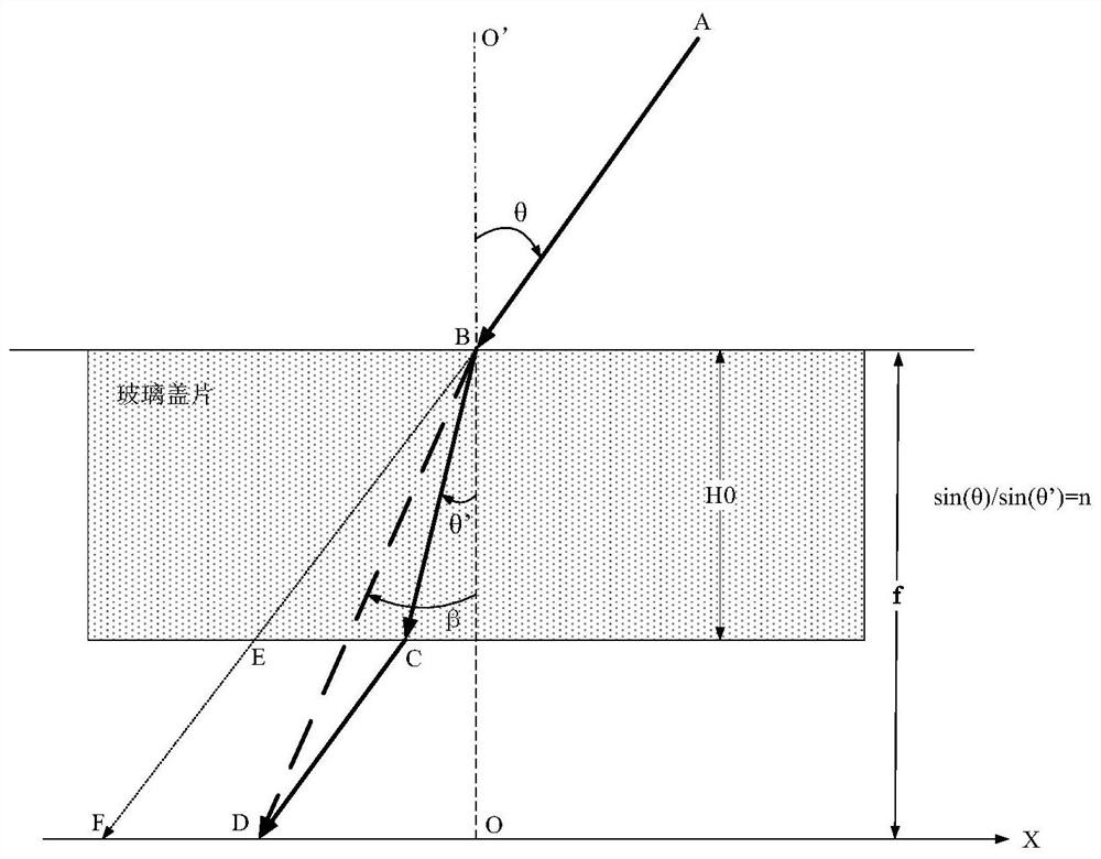
technical field [0001] The invention relates to the field of optoelectronic technology, in particular to a method for correcting distortion of a refractive index model based on single parameter fitting. Background technique [0002] Many optical sensor lenses are equipped with a protective glass cover. When the light passes through the glass cover, it will be refracted, causing refraction of the optical path, which will cause distortion of the image or the coordinates of the light point, affecting the image quality or the calculation accuracy of the light point coordinates. . [0003] Taking the field of aerospace control systems as an example, the digital sun sensor (detector) is a high-precision sensor that measures the sun’s azimuth and direction. It can usually be used with the horizon to determine the two-vector attitude of the satellite to determine the satellite’s three-axis high-precision attitude. As a sun orientation attitude sensor. [0004] When sunlight passes...

Claims


Application Information

Patent Timeline
IPC IPC(8): G06T5/00
CPCG06T2207/10052G06T5/80
Inventor 叶立军王静吉丰保民陈银河袁彦红
Owner SHANGHAI AEROSPACE CONTROL TECH INST
Learn More