A wood drying equipment for wood preservation
A drying equipment and wood preservative technology, applied in drying, drying machine, lighting and heating equipment and other directions, can solve the problems of high cost, cumbersome process, unsatisfactory drying effect, etc., and achieve better drying efficiency. Effect
- Summary
- Abstract
- Description
- Claims
- Application Information
AI Technical Summary
Problems solved by technology
Method used
Image
Examples
Embodiment 1
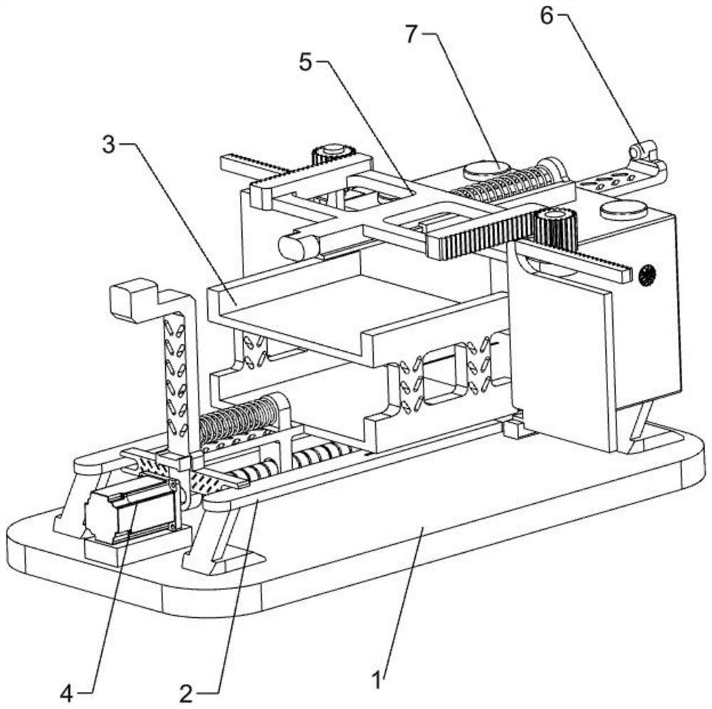
[0066] A wood drying equipment for wood preservation, such as figure 1 As shown, it includes a bottom plate 1, a drying mechanism 2, a moving mechanism 3 and a propulsion mechanism 4, the top of the bottom plate 1 is provided with a drying mechanism 2, the drying mechanism 2 is provided with a moving mechanism 3, and the top of the bottom plate 1 is provided with a propulsion mechanism 4 .
[0067] When the wood needs to be dried, the staff can place the wood on the moving mechanism 3, and then push the moving mechanism 3 to move to the right, thereby driving the wood into the drying mechanism 2, and then the components in the drying mechanism 2 can be activated. , and then dry the wood. After the drying is completed, people take out the wood and close the drying mechanism 2 .
Embodiment 2
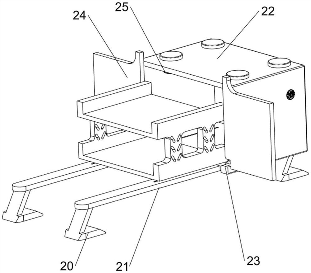
[0069] On the basis of Example 1, as Figure 2-3 As shown, the drying mechanism 2 includes a bracket 20, a support plate 21, an oven 22, a mounting slot 23, an oven door 24 and a heater 25. The top of the bottom plate 1 is provided with brackets 20 on the left, right, front and rear, and the brackets 20 on the left and right sides are provided with brackets 20. A support plate 21 is connected between them, an oven 22 is connected between the right side of the support plate 21, an installation groove 23 is provided on the front and rear sides of the lower left side of the oven 22, and an oven door 24 is arranged on the installation groove 23. Four heaters 25 are provided on the inner wall of the oven 22 .
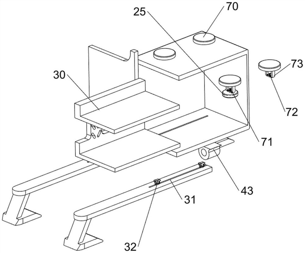
[0070]The moving mechanism 3 includes a material rack 30 , guide rails 31 and rollers 32 , guide rails 31 are provided on the top right side of the support plates 21 on both sides, and a plurality of rollers 32 are slidably arranged on the guide rails 31 on both sides, and m...
Embodiment 3
[0073] On the basis of Example 2, as Figure 3-4 As shown, a propulsion mechanism 4 is also included. The propulsion mechanism 4 includes a first mounting seat 40, a motor 41, a screw rod 42, a first bearing seat 43, a movable frame 44, a guide plate 45, a connecting frame 46 and a first spring 47. , the top left side of the bottom plate 1 is provided with a first mounting seat 40, the top of the first mounting seat 40 is provided with a motor 41, the bottom of the oven 22 is provided with a first bearing seat 43, and the first bearing seat 43 is matched with a screw rod 42 , the left end of the screw rod 42 is connected with the output shaft of the motor 41, the left side of the screw rod 42 is equipped with a movable frame 44, the lower part of the movable frame 44 is provided with a guide plate 45, and the two ends of the guide plate 45 are slidably connected with the support plates 21 on both sides The left side of the screw rod 42 is provided with a connecting frame 46, t...
PUM
 Abstract
Description
Claims
Application Information
 - R&D
- Intellectual Property
- Life Sciences
- Materials
- Tech Scout
- Unparalleled Data Quality
- Higher Quality Content
- 60% Fewer Hallucinations
Browse by: Latest US Patents, China's latest patents, Technical Efficacy Thesaurus, Application Domain, Technology Topic, Popular Technical Reports.
© 2025 PatSnap. All rights reserved.Legal|Privacy policy|Modern Slavery Act Transparency Statement|Sitemap|About US| Contact US: help@patsnap.com


