
A high-speed combined seal for a gearbox

A combined seal and gearbox technology, which is applied in the direction of engine seals, mechanical equipment, engine components, etc., can solve problems such as scrapping, lubrication medium leakage, and gearbox damage, and achieve a wide range of applications, stable performance, and high reliability. Effect

Active Publication Date: 2022-04-08
中国船舶重工集团公司第七0三研究所
View PDF8 Cites 0 Cited by
  • Summary
  • Abstract
  • Description
  • Claims
  • Application Information

AI Technical Summary

Problems solved by technology

If the seal fails, it may cause energy waste and environmental pollution. If external dust particles enter the gearbox, it may cause damage to the gearbox or even scrap it.
Due to the small pressure difference between the internal pressure of the gearbox and the external pressure, the commonly used sealing methods are divided into dynamic sealing methods such as contact seals and non-contact seals. The contact seal is generally that the dynamic part of the seal is in contact with the static part. , to achieve the sealing effect; the non-contact seal generally separates the dynamic part of the seal from the static part, and relies on the centrifugal force and pressure difference between the two to achieve the sealing effect. Since the rotating part and the fixed part do not contact each other, There is no loss, so the service life is long, and generally does not need to be replaced, but the pure single sealing method often cannot achieve a good sealing effect, especially in the application of high-speed gearboxes, the leakage of the lubricating medium occurs from time to time

Method used


Image

  • A high-speed combined seal for a gearbox
  • A high-speed combined seal for a gearbox
  • A high-speed combined seal for a gearbox

Examples


Embodiment Construction

[0014] The present invention is described in more detail below in conjunction with accompanying drawing example:

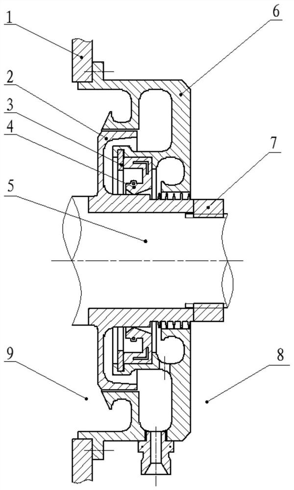
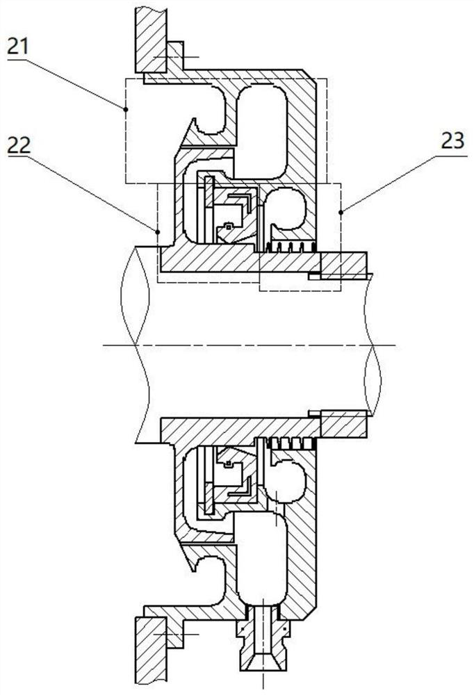
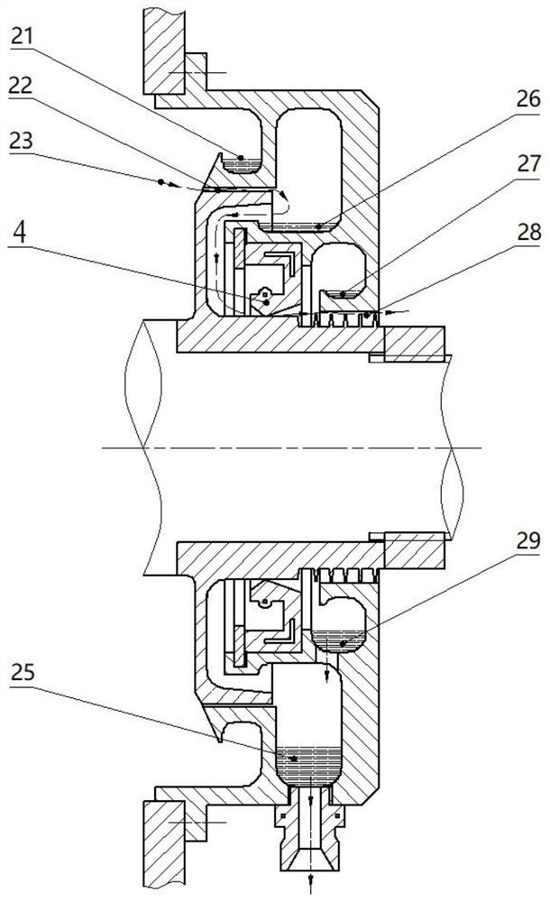
[0015] The technical scheme adopted by the present invention to solve the technical problem is: the seal adopts 13 kinds of sealing combinations of narrow gap oil collecting seal 11, lip seal 12, and oil collecting labyrinth seal. The moving ring 2 of this sealing structure is installed on the rotating shaft 5 of the gearbox, the narrow gap retaining ring 3 and the labyrinth sealing teeth are arranged on the moving ring 2, the static ring 6 of this seal is installed on the box body 1, and the static ring 6 The static ring of the narrow-gap oil-collecting seal 11 and the inner and outer two oil-collecting grooves are arranged on the top. The external oil-collecting groove can be divided into an upper groove body and a lower groove body. The third oil collection tank is set at the position, and the same oil collection tank can be divided into an upper tank body and ...


PUM


Abstract

The purpose of the present invention is to provide a high-speed combined seal for gear boxes, including a box body, a static ring, a moving ring, a rotating shaft, a retaining ring, and a lip seal. The static ring is fixed on the box body, and the moving ring is connected to the rotating The shaft is fixed, the first-third extension end is set on the inner side of the outer wall of the static ring, and the narrow space extension end is set on the outer side of the inner wall of the moving ring. The first extension end itself forms an internal oil collection groove, and the first extension end and the narrow space extension A narrow space is formed between the outlet ends, the second extension end itself forms the first oil collection groove, a lip seal is installed between the second extension end and the inner wall of the moving ring, the third extension end itself forms the second oil collection groove, and the third extension end itself forms a second oil collection groove. A labyrinth seal is set between the protruding end and the inner wall of the moving ring. The invention adopts a multi-layer oil collection tank structure, which can effectively prevent the internal lubricating oil from leaking out of the gearbox and effectively block the external dust particles. It is a product with wide application range, high efficiency, stable performance and high reliability. New technology, especially suitable for shaft seals of high-speed gearboxes.

Description

technical field [0001] The present invention relates to a seal, in particular to a gearbox seal. Background technique [0002] Gearboxes are important equipment widely used in industries, ships, aviation and other fields. During the design process of gearboxes, the internal cleanliness of the gearboxes is required to be very high during operation. At the same time, the lubricating oil of gears and bearings will A large amount of splash is generated. In order to prevent the internal lubricating oil from leaking out and prevent external dust, water vapor, etc. from entering the inside of the gearbox, the rotating shaft system of the gearbox will be sealed with different sealing structures. If the seal fails, it may cause waste of energy and environmental pollution. If external dust particles enter the inside of the gearbox, it may also cause damage to the gearbox or even scrap it. Due to the small pressure difference between the internal pressure of the gearbox and the extern...

Claims


Application Information

Patent Timeline
Patent Type & Authority Patents(China)
IPC IPC(8): F16J15/3232F16J15/16F16J15/447
CPCF16J15/3232F16J15/16F16J15/447
Inventor 孙向志蒋立冬杨龙王志强岳彦炯
Owner 中国船舶重工集团公司第七0三研究所
Learn More