


Quick Research
Generate reliable direction feasibility study reports for your R&D in just a few steps.

Technical Q&A
Discover and master advanced knowledge NOW. Basics, ideas, possibilities, all at once.

Find Solutions
As an expert in R&D theories, this can generate solutions to your technical problems instantly.

Evaluate Feasibility
Analyze your overall solution with one click, know your potential R&D risks in advance.

Monitor Landscape
Get weekly tech updates, stay abreast of the latest tech innovations and key insights.
Tension-controllable rope connecting device and design method
A connecting device and rope technology, which is applied in the direction of mechanical equipment, transmission elements or pulley ropes or cables, belts/chains/gears, etc. Control effects for accurate effects
- Summary
- Abstract
- Description
- Claims
- Application Information
AI Technical Summary
Problems solved by technology
Method used
Image

Examples
Embodiment 1
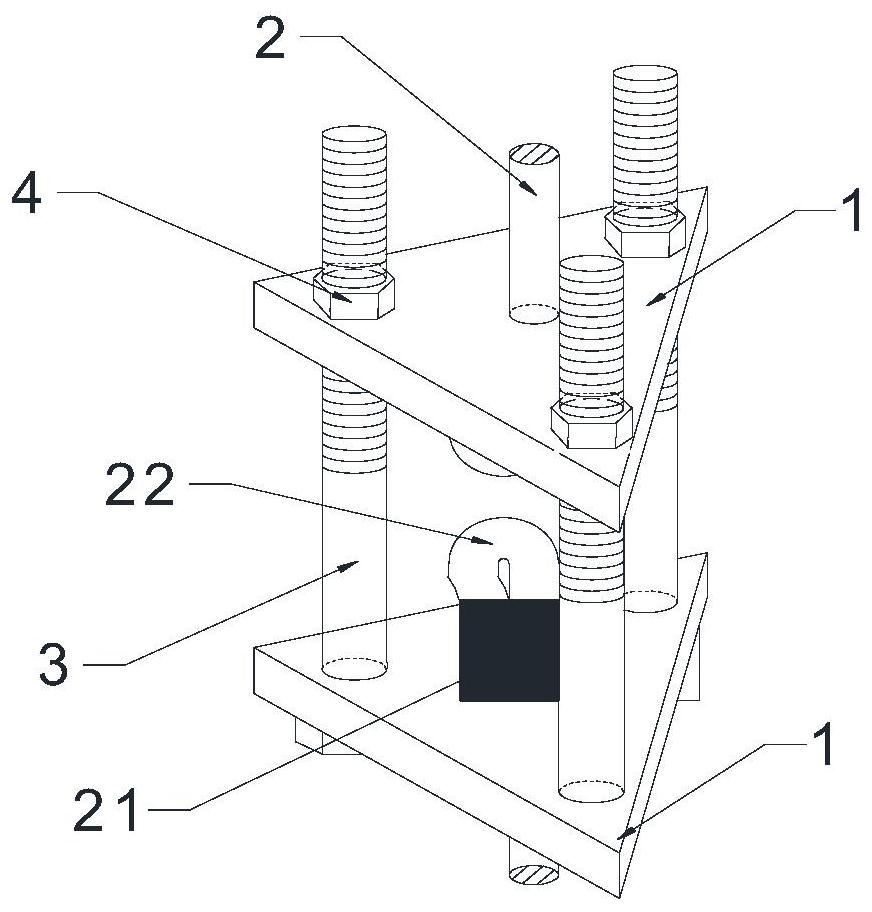
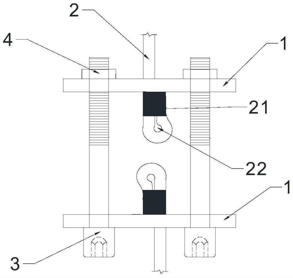
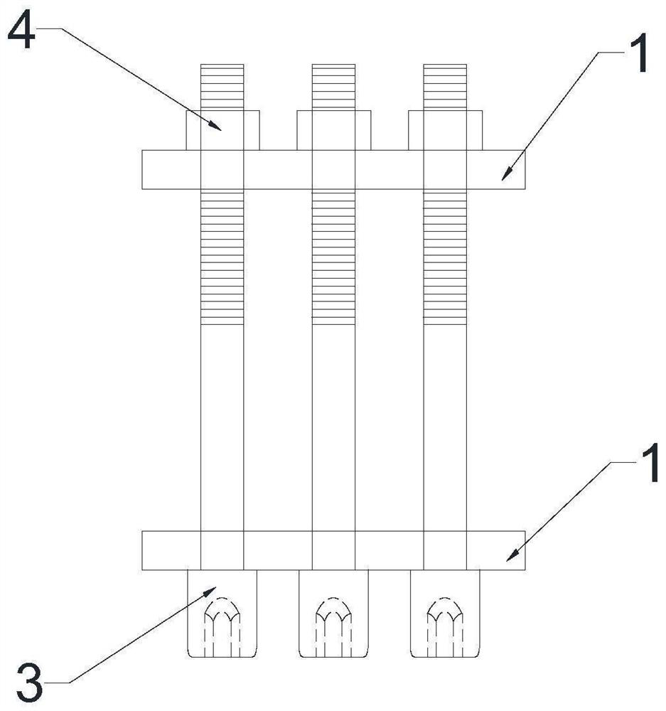
[0031] Such as Figure 1-5 As shown, a tension controllable rope connection device includes two connection plates 1, two metal buckles 21, a rope 2 and three bolts (including three screws 3 and three nuts 4), two connection plates 1 is provided with a rope hole 12 and three screw 3 holes, the three screw 3 holes are respectively arranged around the rope hole 12, the rope 2 passes through the rope holes 12 of the two connecting plates 1, and the two ends of the rope 2 are folded in half Form ring cord 22 afterward, aluminum buckle is pressed on ring cord 22 through press again, and the diameter of ring cord 22 is greater than the diameter of rope hole 12, passes rope hole 12 as restriction ring cord 22. After the rope 2 circles around the support, the sides of the two connecting plates 1 near the ring rope 22 are connected by three bolts.
[0032] The connecting plate 1 is used to limit and connect the two ends of the rope 2. The connecting plate 1 is made of Q235 steel plate....
Embodiment 2
[0047] Except for the following technical features in this embodiment, other technical features are the same as those of Embodiment 1:
[0048] The rope 2 in this embodiment uses a shape-memory alloy rope instead of a steel wire rope, and the shape-memory alloy has a super recovery ability.
[0049] The metal buckle 21 in this embodiment uses a steel buckle instead of an aluminum buckle, and the strength of the steel buckle is even higher.
[0050] Such as Figure 6 As shown, the number of screw holes 11 on the connecting plate 1 in this embodiment is replaced by two instead of three, and the shape is rectangular instead of triangular.
[0051] The formula of step S2 in the design method of a tension controllable rope 2 connection device in this embodiment is: In the formula, σ is the normal stress of the section of the connecting plate 1; R is the radius of the screw 3; r is the radius of the rope 2; L is the length of the connecting plate 1; b is the width of the connecti...
Embodiment 3
[0053] Except for the following technical features in this embodiment, other technical features are the same as those of Embodiment 1:
[0054] Such as Figure 7 As shown, the number of screw holes 11 of the connecting plate 1 in this embodiment is changed from four to three, and the shape is square instead of triangular.
PUM
 Abstract
Description
Claims
Application Information
 - R&D Engineer
- R&D Manager
- IP Professional
- Industry Leading Data Capabilities
- Powerful AI technology
- Patent DNA Extraction
Browse by: Latest US Patents, China's latest patents, Technical Efficacy Thesaurus, Application Domain, Technology Topic, Popular Technical Reports.
© 2024 PatSnap. All rights reserved.Legal|Privacy policy|Modern Slavery Act Transparency Statement|Sitemap|About US| Contact US: help@patsnap.com