
Automatic separation technology for thin rod plates

An automatic separation and thin rod technology, applied in the field of medical care, can solve the problems of a single thin rod a, the end of the thin rod a is broken on the horizontal plate b, unfavorable batch feeding of thin rods and plates, etc., and achieve high rotation accuracy Effect

Active Publication Date: 2021-04-02
WENZHOU CENT HOSPITAL
View PDF5 Cites 0 Cited by
  • Summary
  • Abstract
  • Description
  • Claims
  • Application Information

AI Technical Summary

Problems solved by technology

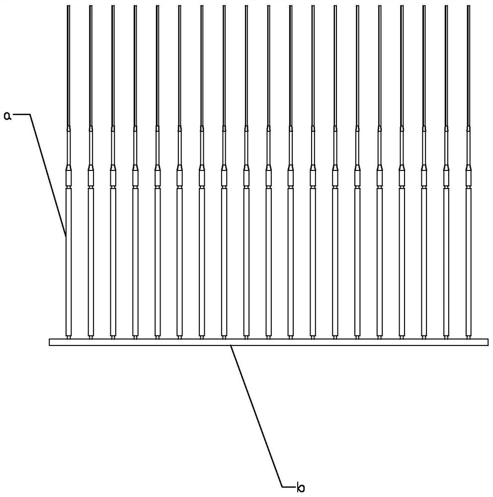
[0003] The thin rods are made of various materials. For the preparation of plastic thin rods, the thin rod plates are generally produced by injection molding. The thin rod plates are connected by several thin rods a on a horizontal plate b, and then the thin rods a The horizontal plate b is separated from each other to obtain a single thin rod a. At present, for the separation of the thin rod plate, the thin rod a is directly separated from the horizontal plate b, and the manual separation is easy to cause the end of the thin rod a to break in the On the horizontal plate b, the length of the thin rod a is different, so that the thin rod a is scrapped. For the equipment that automatically separates the thin rod and plate a, due to the special shape of the thin rod and plate, it is not conducive to batch feeding of the thin rod and plate

Method used


Image

  • Automatic separation technology for thin rod plates
  • Automatic separation technology for thin rod plates
  • Automatic separation technology for thin rod plates

Examples


Embodiment Construction

[0057] The technical solutions of the present invention will be clearly and completely described below in conjunction with the accompanying drawings. Apparently, the described embodiments are some of the embodiments of the present invention, but not all of them. Based on the embodiments of the present invention, all other embodiments obtained by persons of ordinary skill in the art without making creative efforts belong to the protection scope of the present invention.

[0058] In the description of the present invention, it should be noted that the terms "center", "upper", "lower", "left", "right", "vertical", "horizontal", "inner", "outer" etc. The indicated orientation or positional relationship is based on the orientation or positional relationship shown in the drawings, and is only for the convenience of describing the present invention and simplifying the description, rather than indicating or implying that the referred device or element must have a specific orientation, ...


PUM


Abstract

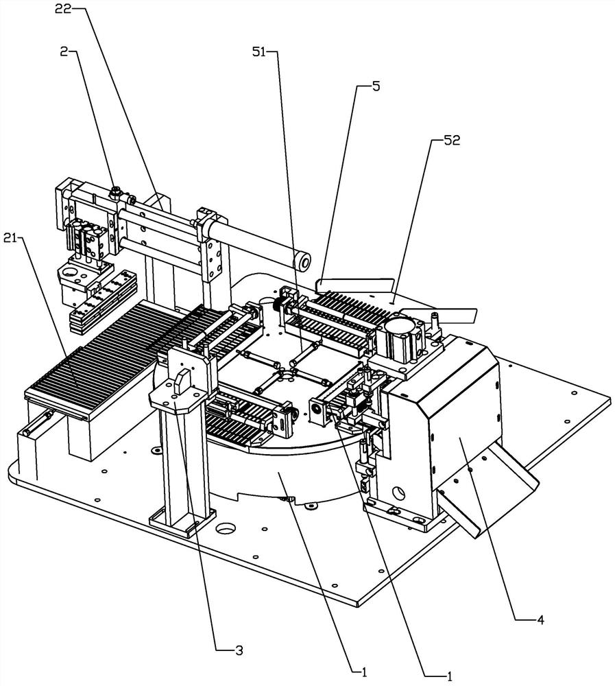
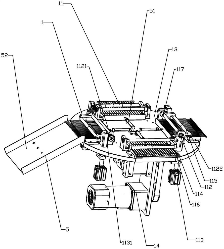
The invention relates to an automatic separation technology for thin rod plates. According to the technology, the thin rod plates are included; each thin rod plate is divided into a plurality of thinrods and a transverse plate, and the transverse plate is used for connecting the end parts of the plurality of thin rods; and an index plate conveying device for realizing conveying of the thin rod plates among devices. The technology comprises the following steps that a, a one-by-one feeding device conveys the batched thin rod plates to a clamping mechanism one by one; b, a clamping mechanism isarranged on the index plate conveying device and used for clamping the thin rod plates and conveying the thin rod plates to all the devices; c, a positioning device positions the thin rod plates on the clamping mechanism and pushes the thin rod plates to a required position; d, a separating device separates the thin rods from the transverse plates on the clamping mechanism; and e, a thin rod unloading device pushes the thin rods on the clamping mechanism out of the clamping mechanism. The invention provides the automatic separation technology for the thin rod plates.

Description

technical field [0001] The invention relates to the field of medical care, in particular to an automatic separation process for thin rods and plates. Background technique [0002] With the improvement of the quality of life, people pay more and more attention to the care of the body, and the regular cleaning of the ears is also very important. At present, there are many ways to clean the ears. Unlike ear picks, which are easy to cause damage to the ears, and unlike liquid cleaning that may cause infection, goose feather sticks are gentle on ears, and at the same time can bring people a comfortable feeling. Goose feather sticks can be divided into two types according to their structure. Cleaned absorbent cotton and thin rods to support the absorbent cotton. [0003] The thin rods are made of various materials. For the preparation of plastic thin rods, the thin rod plates are generally produced by injection molding. The thin rod plates are connected by several thin rods a on ...

Claims


Application Information

Patent Timeline
IPC IPC(8): B65G47/90B65G47/52B65G47/34
CPCB65G47/90B65G47/52B65G47/34
Inventor 黄力鹏陈芒芒吕杨训
Owner WENZHOU CENT HOSPITAL
Learn More